Preface
Welcome to Stambia!
This guide contains information about using the product to design and develop a Data Integration project.
Tip: If you simply want to learn about Stambia and see what Stambia is all about, visit the Stambia website.
Audience
This document is intended for users interested in using Stambia for their Data Integration Initiatives : Business Intelligence, Data Migration, E-commerce projects, Web Services, etc..
Document Conventions
This guide uses the following formatting conventions:
| Convention | Meaning |
|---|---|
| boldface | Boldface type indicates graphical user interface associated with an action, or a product specific term or concept. |
| italic | Italic type indicates special emphasis or placeholder variable that you need to provide. |
monospace |
Monospace type indicates code example, text or commands that you enter. |
Other Stambia Resources
In addition to the product manuals, Stambia provides other resources available on its company website: www.stambia.com and community website www.stambia.org.
Obtaining Help
To get help you can:
- contact our global Technical Support Center: www.stambia.org/di/support.
- consult the articles on our community website www.stambia.org.
- consult or post topics on our forum on www.stambia.org.
Feedback
We welcome your comments and suggestions on the quality and usefulness of this documentation.
If you find any error or have any suggestion for improvement, please contact us at www.stambia.org/di/support and indicate the title of the documentation along with the chapter, section, and page number, if available. Please let us know if you want a reply.
Introduction to Stambia Designer
Opening the Stambia Designer
To open the Stambia Designer:
- In the Stambia menu, click on the
stambiashortcut. - The Stambia Designer opens.
Stambia Designer Overview
The Stambia Designer appears as follows.
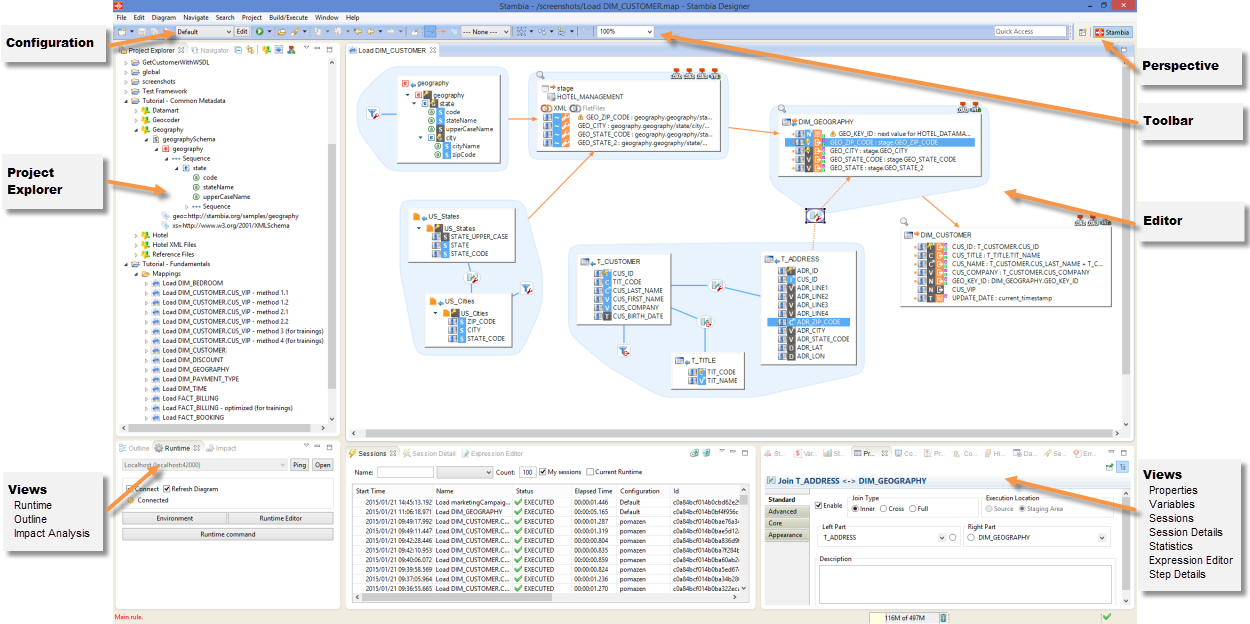
In the Stambia Designer, the following sections are available:
- The Project Explorer view provides a hierarchical view of the resources. From here, you can open files for editing or select resources for operations such as exporting.
- The Editors ' section contains the various objects being edited: Mappings, Metadata, Processes, etc...
- Various other Views are organized around the edition view and allow navigating, viewing and editor object properties.
- The Configuration zone allows selecting the active Configuration (development, production, etc.).
- You can use the Perspectives to customize the layout of the various views in the Stambia Designer. A default Stambia perspective is created and it is possible to customize your own perspectives.
Design-Time Views
The following section describes the main views used at design-time.
The Project Explorer
The Project Explorer contains a hierarchical view of the resources in the workspace.
These resources are organized into projects and folders.
The following types of resources appear in the projects:
| Resource Type | File Extension | Description |
|---|---|---|
| Metadata | .md | A metadata resource describes source or target systems and datastores or variables that participate in a mapping or a process. |
| Mapping | .map | A mapping is used to load data between source and target datastores. |
| Process | .proc | A process is a sequence of tasks and sub-tasks that will be executed during run-time. Certain processes are Template Processes, which are used to generate a process from a mapping. |
| Templates Rules | .tpc | Templates Rules file describe the conditions upon which template processes can be used. For example, an Oracle integration template can be used when integrating data to a target datastore in an Oracle database, but is not suitable when targeting XML files. |
| Configuration Definition | .cfc | A configuration makes the metadata variable. For example, configurations can contain the connection information to the data servers and you can use configurations to switch between production and development environments. |
| Runtime Definition | .egc | Definition of a Runtime engine. A Runtime engine executes the integration processes created with the Stambia Designer. |
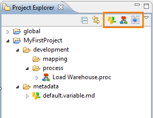
From the project explorer toolbar (highlighted in the previous screenshot) you can create the three main types of design-time resources: Metadata, Mappings and Processes.
Duplicate resources
Multiple resources with the same ID, called duplicates, can exist in the same Workspace.
Only one can be active at the same time, and is indicated with an asterisk at the end of the name:
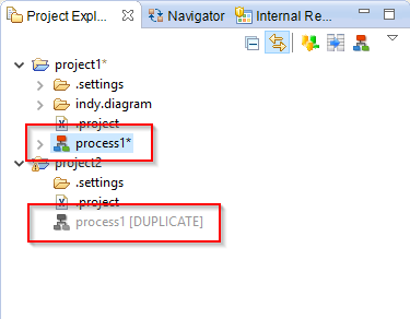
To enable a duplicate:
- Right click on it and select Enable Duplicate Model.
- The duplicated resource will become the active one.
Moreover, the Manage Duplicate Resource tool in the Impact View permits to manage the duplicates of the whole workspace.
The Properties View
The Properties view displays the list of properties of the object currently selected.
The Expression Editor
The Expression Editor displays code related to the object being edited. For example, the mapping expressions, the code of the actions, etc.
This editor provides two options:
- Lock: Allows you to lock the expression editor. When this option is not-selected the expression editor changes every time you select an element in the Stambia Designer to display the code of this element. To build expressions in the expression editor using drag-and-drop, you can select the element that you want to edit (for example, a target mapping), select the lock option and then drag and drop columns from the various source datastores of the mapping into the expression editor.
- Auto-Completion: This option enables auto-completion in the code. While editing, press CTRL+SPACE to have the list of suggestions for your code.
The Outline View
The Outline view provides a high-level hierarchical or graphical view of the object currently edited.
Moreover, it provides a search tool  , which permits to search into the current object.
The Impact View
The Impact view allows you to analyze the usage of an object in the project and perform impact analysis and cross-referencing.
To use the Impact Monitor:
- Select the object that you want to analyze. The Impact view displays the list of usages for this object.
- Double-click on one of the objects in the list to open it for edition.
The Impact Menu offers several tools:
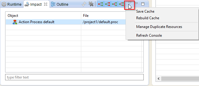
Save Cache and Rebuild Cache are used to explicitly refresh or save the cross-references cache for your workspace. In the normal course of operations, the cache is automatically refreshed.
Manage Duplicate Resource opens a new windows to manage the duplicated resources of the workspace.
Refresh Console refreshes the cache console (re-calculates mappings states, files states, cross-references, ...).
The Run-Time Views
Three views are used to monitor the run-time components and executions of the sessions.
The Runtime View
The Runtime view allows monitoring of a Runtime Engine.
From this view, you can perform the following operations:
- Click on the Environment button to start and stop a local (pre-configured) Runtime engine and demonstration databases.
- Click on the Runtime Editor button to add or modify Runtime engine definitions. The procedure to create a Runtime engine definition is described below.
- Check that a Runtime engine is active by selecting it in the list and clicking Ping.
- Connect a Runtime engine: Select it in the list and then Click on the Connect option. When a Runtime engine is connected, it is possible to view its sessions and issue commands to it via its command-line console.
- When connected to a Runtime engine, you can activate the Refresh Diagram option. When this option is active, you can monitor on the diagram of a process this process' activity as it runs in the Runtime engine.
- When connected to a Runtime engine, Click on the Runtime Command button to open its command-line console. From the Console you can issue commands to the Runtime engine. Type
helpin the console for a list of valid commands.
To create a new Runtime definition:
- In the Runtime view, Click on the Runtime Editor button. The Runtime definition (conf.egc) opens.
- Select the root node, right-click and select New Child > Engine.
- In the Properties view, enter the following information:
- Description: Description of this Runtime.
- Name: User-friendly name for the run-time.
- Server: Host name of IP address of the machine where the Runtime components run.
- Port: Port on this machine where the Runtime runs.
- Press CTRL + S to save the new Runtime definition.
The Sessions View
The Sessions view displays the list of sessions of the connected Runtime engine.
In this view, you can filter the sessions using parameters such as the session Name or Status, filter a number of sessions, or only the session started by the current user. If the log is shared by several Runtime engines, it is also possible to filter only sessions of the current Runtime engine.
From this view, you can also purge the log by clicking the Delete All and Delete Until buttons.
The list of sessions includes the following session properties:
- Start Time: Startup day and time of the session.
- Name: Name of this session.
- Status: Status of the session.
- Elapsed Time: Duration of the session.
- ID: Unique identifier of the session.
- Log Name: Name of the log storing this session.
- Log Type: Type of the log storing this session.
- Engine: Name of the Runtime engine processing the session.
- Guest Host: Name of the host from which the session was initiated.
- Launch Mode: Method used to start the session: Stambia Designer, Web Service, Scheduler, etc.
- Execution Mode: Memory or command line.
Statuses
| Status | Description |
|---|---|
| Prepared | Prepared but not executed sessions. |
| Running | Running sessions. |
| Executed | Executed sessions. |
| Error | Sessions in error. |
| Killed | Sessions killed by the user |
| Dead | Dead sessions, that is sessions that never finished and are considered as dead by Stambia Analytics |
Launch Modes
| Launch Mode | Description |
|---|---|
| Designer | The session has been executed from the Designer. |
| Schedule | The session has been executed automatically by a schedule. |
| Web Interactive | The session has been executed from Analytics. |
| Engine Command | The session has been executed from the Runtime Command utility (E.g. Using the ‹execute delivery› command). |
| Command Line | The session has been executed from command line (E.g. with startdelivery.bat). |
| Web Service | The session has been executed from the Runtime’s REST or SOAP web services. |
| Action | The session has been executed from the ‹Execute Delivery› Process Action. |
| Restart | The session has been restarted. |
Execution Modes
| Execution Mode | Description |
|---|---|
| Memory | The session has been executed in memory in the Runtime. |
| Autonomous | The session has been executed outside of the Runtime. |
The Session Detail View
This view displays the details of the session selected in the Sessions view. The Errors and Warning tabs display the list of issues, and the Variables tab displays the list of session and metadata variables.
Standard session variables include:
- CORE_BEGIN_DATE: Startup day and time of the session.
- CORE_DURATION: Duration of the session in milliseconds
- CORE_END_DATE: Day and time of the session completion.
- CORE_ENGINE_HOST: Host of the Runtime engine processing the session.
- CORE_ENGINE_PORT: Port of the Runtime engine processing the session.
- CORE_ROOT: Name of the process containing the session.
- CORE_SESSION_CONFIGURATION: Configuration used for this execution.
- CORE_SESSION_ID: Unique identifier of the session.
- CORE_SESSION_NAME: Name of this session.
- CORE_SESSION_TIMESTAMP: Session startup timestamp.
- CORE_TEMPORARY_FOLDER: Temporary folder for this session.
The Statistics View
The Statistics displays the list of statistics aggregated for the sessions.
The following default statistics are available:
- SQL_NB_ROWS: Number of lines processed.
- SQL_STAT_INSERT: Number of lines inserted.
- SQL_STAT_UPDATE: Number of lines updated.
- SQL_STAT_DELETE: Number of lines deleted.
- SQL_STAT_ERROR: Number of errors detected.
- OUT_FILE_SIZE: Output file size.
- OUT_NB_FILES: Number of output files.
- XML_NB_ELEMENTES: Number of XML elements processed.
- XML_NB_ATTRIBUTES: Number of XML attributes processed.
This view can be parameterized via the preferences (Window > Preferences), in the Stambia > Monitor section.
You can select which of the variables need to be aggregated using which aggregate function.
The Step Detail View
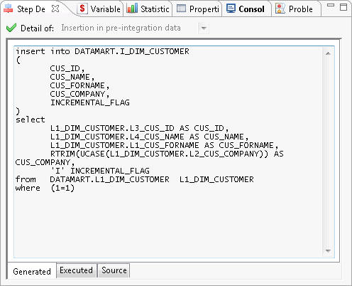
This view displays the details of the steps executed in a session.
It displays the code at various stages in three tabs:
- Source displays the source code before generation. It comes from the process templates.
- Generated displays the generated code. It may contain dynamic values replaced before execution.
- Executed displays the executed code with the variables replaced.
The Detail Of selection box allows you to select one of the iterations of a step that was executed several times.
The Variable View
The Variable view displays the variables for the selected step. The list of variables depends on the steps. The following standard variables appear for all steps:
- CORE_BEGIN_DATE: Startup day and time of the step.
- CORE_DURATION: Duration of the step in milliseconds
- CORE_END_DATE: Day and time of the step completion.
- CORE_BEGIN_ACTION: True if this action is a start action.
- CORE_NB_ENABLED_EXECUTIONS: Maximum number of executions allowed for this step. This variable is used in loops.
- CORE_NB_EXECUTION: Number of iterations of this step.
- CORE_RET_CODE: Return code for this step.
Working with Projects
Resources are organized into projects and folders.
In a Stambia workspace, there are two default projects:
- global contains all the objects global to this workspace, which include:
- The Runtime Engine Definition
- The Configuration Definitions
- The Template Processes are also imported in this project.
Creating Projects
To create a new project:
- Right-click in the Project Explorer and then select New > Project in the context menu. The New Project wizard opens.
- In the Wizards filter, enter Project, and then select the General > Project item in the tree.
- Click Next.
- Enter a Project Name and then click Finish.
Creating Folders
To create a new folder:
- Right-click on a project or folder in the Project Explorer and then select New > Folder in the context menu. The New Folder wizard opens.
- Select the parent folder or project in the wizard.
- Enter a Folder Name and then click Finish.
You can organize folders within a project and resources within folders using drag and drop operations or using the Move action in a resource’s context menu.
A typical organization for a project is:
ProjectName(Project)metadata(folder): this folder contains all the metadata resources.development(folder): this folder contains all the development resources.process(folder): this folder contains all the processes.mapping(folder): this folder contains all the mappings.
Importing Templates
Stambia uses Templates to generate the code of processes for the mappings.
Templates are shipped directly within Designer and Components resources, and automatically selected in Mappings.
However, when you want to modify or install a patched Template in your workspace, you can override those easily.
To modify a Template, open Internal Resources View, right-click on the Template you want to modify, and then import it in the workspace.
To import a patched Template you received from your team or from support team, for instance, right-click on the global project and select Import in the context menu. The Import wizard opens. Then import your Template with corresponding entry in the tree. (For instance, if you received it zipped in an archive, choose Archive File).
Version Control
The Stambia workspace and the projects use exclusively file storage. They can be version controlled using a version control system compatible with Eclipse RCP, for example Subversion. Refer to the version control system documentation for more information.
Sample Projects
To help you starting with the Designer and its various Components, Stambia offers Sample Projects which demonstrates some use cases.
Those Projects are shipped directly within Components, and automatically available in the Designer when you are installing them.
Some are already available on a default installation, and some will be added automatically when installing corresponding Components.
You can import a Sample Project in your workspace from the Welcome page (Menu Help / Welcome):
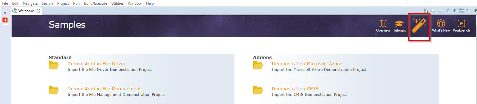
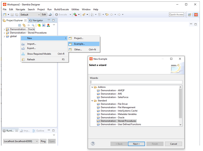
You can also import a Sample Project in your workspace when creating a Project.
Right click in Project Explorer, then choose New > Example or New > Project > Examples:
Working with Metadata
What is a Metadata?
Stambia uses Metadata to design, generate and run the data integration processes. For example, the structure of the tables, text or XML files taken into account in the data integration flows.
A Metadata file  handled by Stambia represents generally a data model. For example a database schema, a folder, etc, storing tables, files.
A Metadata file is created most of the time by connecting to the database server, file system, etc, to retrieve the structure of the tables, files, etc.. This mechanism is called reverse-engineering.
The following sections explain how to create Metadata with examples for the three main types of Metadata files.
Creating a new Metadata
To create a new Metadata click on the New Metadata button in the Project Explorer toolbar.
Note that you can also use File > New > Metadata menu or the right click context menu in Project Explorer.
Metadata Creation Wizard will opens to let you which type of Metadata you want to create.
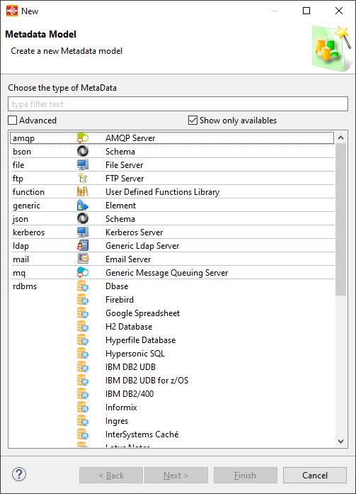
Simply choose the Metadata corresponding to the technology, and then press Next.
On next step choose the parent Project / folder in which you want to create the Metadata.
Then choose a Name for your Metadata.
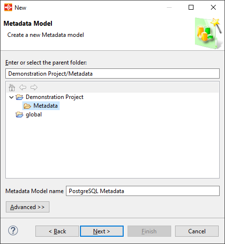
Then you can click on Finish if possible or on Next.
This depends on the type of Metadata, some require an additional step to define a Module.
If it is the case, an additional step will appear to let you select the Module to be used for your Metadata.
Refer to Working with Modules documentation for further information about Modules.
Finally, when the creation wizard closes, the Metadata will be created and you will be able to proceed to the configuration of your Metadata.
Depending on the type of Metadata created, additional wizards may open to help you reversing database structure, etc. Examples of Metadata creation with different type of Metadata can be found below.
Metadata Examples
You can find below examples of Metadata creation for different types of Metadata.
Defining a Database Model
Creating and Reversing a Database Model
This process uses a wizard that performs three steps:
- Create a new data server
- Create a new schema
- Reverse-engineer the datastores
To create a new data server:
- Click on the New Metadata button in the Project Explorer toolbar. The New Model wizard opens.
- In the Choose the type of Metadata tree, select RDBMS > <DBMS Technology> where <DBMS Technology> is the name of the DBMS technology that you want to connect.
- Click Next.
- Select the parent folder or project for your new resource.
- Enter a File Name and then click Next.
- Choose a Module :Working-with-Modules.html and then click on Finish.
- The Server wizard opens.
- In the Server Connection page, enter the following information:
- Name: Name of the data server.
- Driver: Select a JDBC Driver suitable for your data server.
- URL: Enter the JDBC URL to connect this data server.
- User: The database user name, if any
- Password: This user’s password, if any
- (Optional) AutoCommit: Stambia Designer connections to this data server are autocommit connections. This is only used for the connections the Designer will perform on this database for reverse-engineering for instance.
- Click on the Connect button to validate this connection and then click Next. The Schema Properties page opens.
To create a new schema:
- In the Schema Properties page, enter the following information:
- Name: Use the checkbox to enable this field, and enter a user-friendly name for this schema.
- Schema Name: Click on the Refresh Values button to retrieve the list of schemas from the database, and then select one of these schemas.
- Reject Mask: Set the table name mask for the table containing the load rejects (error tables). See the Table Name Masks section below for more information.
- Reject Mask: Set the table name mask for the temporary load tables. See the Table Name Masks section below for more information.
- Integration Mask: Set the table name mask for the temporary integration tables. See the Table Name Masks section below for more information.
- Work Schema: Select a schema for storing the load and integration temporary tables for this data server. This schema is also referred to as the Staging Area. See the Work and Reject Schema Selection section for more information. Click on the ... button to create a new schema definition and set it as the work schema.
- Reject Schema: Select a schema for storing the errors (rejects) tables for this data server. See the Work and Reject Schema Selection section for more information. Click on the ... button to create a new schema and set it as the reject schema.
- Click Next. The Reverse Datastore page opens.
To reverse-engineer the datastores into a schema:
- In the Reverse Datastore page, optionally set an object filter. Use the
_and%wildcards to represent one or any number of characters. - Optionally filter the type of objects that you want to reverse-engineer: All, synonyms, tables and views.
- Click on the Refresh button to refresh the list of datastores.
- Select the datastores that you want to reverse engineer in the list.
- Click Finish. The reverse-engineering process retrieves the structure of these datastores.
- Press CTRL+S to save the editor.
Adding a New Schema
To add a new schema to an existing data server:
- In the metadata file editor, select the root node.
- Right-click and select Action > Launch DataSchema Wizard.
- Follow the steps described in the "To create a new schema" section of Creating and Reversing a Database Model.
Reverse-engineering an Existing Schema
To retrieve metadata changes from an existing schema, or to retrieve new table definitions, you must perform a new reverse-engineering.
To reverse-engineer an existing schema:
- In the metadata file editor, select the node corresponding to the schema.
- Right-click and select Action > Launch DataSchema Wizard.
- Click Next in the first page of the wizard.
- On the second page follow the steps described in the "To reverse-engineer the datastores in a schema" section of Creating and Reversing a Database Model.
Table Name Masks
Table name masks define name patterns for the temporary objects created at run-time.
Table Name masks can be any string parameterized using the following variables:
[number]: Automatically generated increment for the load tables, starting with 1.[targetName]: Name of the target table of a mapping.${variable}$or%{variable}%: A session variable that is set at run-time.
Note that the resulting string must be a valid table name.
Example: L_[targetName]_[number] would create Load tables named L_CUSTOMER_1, L_CUSTOMER_2, etc for a mapping loading the CUSTOMER table.
Work and Reject Schemas Selection
When defining a schema (with optionally a Name for this schema), you optionally refer to two other schemas, the Work Schema and Reject Schema.
These two schemas store respectively temporary load/integration tables (Staging Area) and the error (reject) tables for the data tables stored in the schema being defined. In the mappings, the work schema is also called the Staging Area.The value for these two schemas may be:
- Empty: In that case, the work schema and reject schemas are automatically set to the Schema Name. This means that the temporary and error tables are created in the same schema as the data tables.
- Set to the Name or Schema Name of another schema. In that case, the temporary or error tables are stored in this other schema’s Schema Name.
Tip: It is recommended to configure by default two separate temporary (for example,
STB_TEMP) and error (for exampleSTB_REJECTS) schemas for each database server and set them as the Work Schema and the Reject Schema for all the data schemas. This avoids mixing application data (data schemas) and Stambia tables in the same schemas.
Creating and using a Metadata Query
A SQL Query can be reversed and used in a database Metadata.
To create a Query:
- Right-click on the database node in the Metadata and select New > Query Folder. It will create a folder in which the queries will be stored.
- Give a name to the query folder which appeared in the Metadata.
- Finally, Right-click on it and select New > Query.
To reverse a Query:
- Give a name to the query.
- Enter a SQL SELECT query in the Expression.
- Save the Metadata.
- Right-click on the query and select Actions > Reverse
Note: The reversed query can be used in Mappings as Source like any other datastores. However, it is not recommended to use it as a Target as it only represents a query and is not a table.
Tip: It is possible to parameterize the query using xpath syntax: {./md:objectPath(ref:schema('schema_name'), 'table_name')} Note that the schema and table must exist on the metadata.
Defining a File Model
Creating a File Model
To create a new File metadata file:
- Click on the New Metadata button in the Project Explorer toolbar. The New Model wizard opens.
- In the Choose the type of Metadata tree, select File > File Server.
- Click Next.
- Select the parent folder or project for your new resource.
- Enter a File Name and then click Finish. The metadata file is created and the editor for this file opens.
- Select the Server node. In the Properties view, set the following properties:
- Name: A user-friendly name for this schema. The Server node is renamed with this name.
- Driver:
com.stambia.jdbc.driver.file.FileDriver - URL:
jdbc:stambia:file
- Right-Click on the root node of your file model editor, and then select Actions > Launch Directory wizard.
- In the Directory page, provide a user-friendly Name for the directory and select its Path.
- Click Next.
- In the File Properties page:
- Use the Browse button to select the file within the directory and set the Physical Name for the file.
- Set a logical Name for the file datastore.
- Select the file Type: Delimited or Positional (fixed width fields).
- Follow the process corresponding to the file type for reverse-engineering.
Reverse-Engineering a Delimited File
To reverse-engineer a delimited file:
- In the File Properties page, use the Refresh button to view the content of the file in the preview. Expand the wizard size to see the file contents.
- Set the following parameters to match the file structure:
- Charset Name: Code page of the text file.
- Line Separator: Character(s) used to separate the lines in the file.
- Field Separator: Character(s) used to separate the fields in a line.
- String Delimiter: Character(s) delimiting a string value in a field.
- Decimal Separator: Character used as the decimal separator for numbers.
- Lines to Skip: Number of lines to skip from the beginning of the file. This count must include the header.
- Header Line Position: Position of the header line in the file.
- Click Next.
- Click Reverse. If the parameters set in the previous page are correct, the list of columns detected in this file is automatically populated.
- Reverse-engineering parses through a number of lines in the file (defined by the Row Limit) to infer the data types and size of the columns. You can tune the reverse behavior by changing the Reverse Options and Size Management properties, and click Reverse again.
- You can manually edit the detected column datatype, size and name in the table.
- Click Finish for finish the reverse-engineering.
- Press CTRL+S to save the file.
Reverse-Engineering a Fixed-Width File
To reverse-engineer a fixed-width file:
- In the File Properties page, use the Refresh button to view the content of the file in the preview. Expand the wizard size to see the file contents.
- Set the following parameters to match the file structure:
- Charset Name: Code page of the text file.
- Line Separator: Character(s) used to separate the lines in the file.
- Decimal Separator: Character used as the decimal separator for numbers.
- Lines to Skip: Number of lines to skip from the beginning of the file. This count must include the header.
- Header Line Position: Position of the header line in the file.
- Click Next.
- Click Refresh to populate the preview.
- From this screen, you can use the table to add, move and edit column definitions for the file. As you add columns, the preview shows the position of the columns in the file.
- Click Finish to finish the reverse-engineering.
- Press CTRL+S to save the file.
Defining an XML Model
To create a new XML metadata file:
- Click on the New Metadata button in the Project Explorer toolbar. The New Model wizard opens.
- In the Choose the type of Metadata tree, select XML > XML Schema.
- Click Next.
- Select the parent folder or project for your new resource.
- Enter a File Name and then click Finish. The metadata file is created and the editor for this file opens.
- Right-Click on the Schema node in the editor and select Actions > Properties.
- In the Name field, enter a name for this schema.
- In the XML Path field, enter the full path to the XML file. This file does not need to physically exist at this location if you have the XSD, and can be generated as part of a data integration process.
- In the XSD Path field, enter the full path to the XSD describing the XML file. If this XSD does not exist, click Generate to generate an XSD from the content of the XML file provided in the XML Path.
- Click Refresh and then select the root element for this schema. If the XSD has several root nodes, it is possible to repeat this operation to reverse-engineer all the hierarchies of elements stored in the XML file. Each of these hierarchies can point to a different XML file specified in the properties of the element node.
- Click Reverse. The reverse-engineering process retrieves the XML structure from the XSD.
Defining a Generic Model
A Generic model is useful when you want to have custom Metadata available in order to parameterize your developments.
To define a Generic Model:
- Click on the New Metadata button in the Project Explorer toolbar. The New Model wizard opens.
- In the Choose the type of Metadata tree, select Generic > Element.
- Click Next.
- Select the parent folder or project for your new resource.
- Enter a File Name for your new metadata file and then click Finish. The metadata file is created and the editor for this file opens.
- Select the Element node and enter the Name for this element in the Properties view.
A Generic Model is a hierarchy of Elements and Attributes. The Attribute values can be retrieved for an element thanks to the Stambia usual Xpath syntax.
To create a new Element:
- Right-Click on the parent element.
- Select New > Element
- In the Properties view, enter the name of the new Element.
To add an attribute to an Element:
- Right-Click on the parent element.
- Select New > Attribute
- In the Properties view enter the Name and the Value of the Attribute. This name will be useful to retrieve the value of your attribute.
Metadata Configurations
What is a Metadata Configuration?
Metadata Configurations allow to parameterize mMtadata for a given context. For example, a single data model declared in Stambia may have two configurations, Production and Development. Used in the Development configuration it would point to a development server and used in the Production configuration it would point to a production server. Both servers contain the same data structures (as defined in the model), but not the same data, and have different connection information.
Creating a Configuration
To create a configuration:
- In the Stambia Designer toolbar, Click on the Edit button.
- The Configuration Definition editor (
conf.cfc) opens. - Right-Click on the root node (Cfc), then select New Child > Configuration.
- In the Properties view, enter the new configuration’s properties:
- Code: Code of the configuration. This code appears in the Configurations drop-down list in the Stambia Designer toolbar.
- Description: Description of the configuration.
- Execution Protection: Set to true if you want to be prompted for a password when executing a process in this configuration.
- Selection Protection: Set to true if you want to be prompted for a password when switching the Stambia Designer to this configuration.
- Password: Protection password for this configuration.
- Press CTRL+S to save the configuration.
Using Configurations
In a metadata file, it is possible to define configuration-specific values for certain properties. The following section describes the most common usage of the configurations in metadata files.
Using Configuration for Databases
In databases, you can customize the connection information to the data server as well as the data schema definitions using configuration.
To create a data server configuration:
- In the database metadata file editor, select the root node corresponding to your data server.
- Right-click and select New Child > DataServer Configuration.
- In the Properties view:
- Select the configuration in the Configuration Name field.
- Set the different values for the connection information (Driver, URL, User and Password) as required.
- Press CTRL+S to save the database metadata file.
To create a data schema configuration:
- In the database metadata file editor, select the node corresponding to your data schema.
- Right-click and select New Child > DataServer Configuration.
- In the Properties view:
- Select the configuration in the Configuration Name field.
- Set different values for the schema information (Schema Name, Reject Schema, etc.) as required.
- Press CTRL+S to save the database metadata file.
Note: You can define configurations at all levels in the database metadata file for example to define configuration-specific structural features for the datastores, columns, etc.
Using Configuration for Files
In files, you can customize the directory location as well as the file names depending on the configuration using a directory or a file configuration.
For example:
- in a development configuration, a file is located in the
C:\temp\directory and namedtestcustomers.txt - in a production configuration, a file is located in the
/prod/files/directory and namedcustomers.txt
To create a directory configuration:
- In the File metadata file editor, select the node corresponding to your directory.
- Right-click and select New Child > Directory Configuration.
- In the Properties view:
- Select the configuration in the Configuration Name field.
- Set a value for the Path specific to the configuration.
- Press CTRL+S to save the File metadata file.
To create a file configuration:
- In the File metadata file editor, select the node corresponding to your file.
- Right-click and select New Child > File Configuration.
- In the Properties view:
- Select the configuration in the Configuration Name field.
- Set a value for the Physical Name of the file specific to the configuration.
- Press CTRL+S to save the File metadata file.
Note: You can define configurations at all levels in the File metadata file for example to define configuration-specific structural features for flat files.
Using Configuration for XML
In XML files, you can customize the path of the XML and XSD files depending on the configuration using a schema configuration.
To create a schema configuration:
- In the XML metadata file editor, select the root node.
- Right-click and select New Child > Schema Configuration.
- In the Properties view:
- Select the configuration in the Configuration Name field.
- Set a value for the XML Path and XSD path specific to the configuration.
- Press CTRL+S to save the XML metadata file.
Note: You can define configurations at all levels in the XML metadata file for example to define configuration-specific structural features in the XML file.
Working with Modules
What is a Module?
When you need to communicate with a technology such as SQL Databases, NoSQL Databases, Cloud Platforms, and more... you will need to use what we call a Module.
What is a Module? A Module is a set of all what is necessary to communicate with a technology.
Which means in the Java world all the libraries files which are required for the communication with the given technology, such as JDBC drivers, API libraries, libraries dependencies, ...
In Stambia you will manage all of those through Modules.
Modules are uniquely identified through their name and can be reused in multiple Metadata.
When should I use a Module?
Using a Module to communicate with a technology is mandatory for most of them, as most require some libraries for communication.
The Module to be used must be defined most of the time directly in your Metadata.
For instance, in your PostgreSQL database Metadata, you’ll need to select a Module for communicating with PostgreSQL.
The Designer will help you to select and create Modules when necessary:
New Metadata
When creating a new Metadata you will have a step where you will choose which Module should be used for the communication.
Existing Metadata
On existing Metadata you can edit the Module used through the «Module» attribute which is on the root node of your Metadata.
Scripting Process Actions
On a Scripting Process Action you can also define a Module if you want to use additional libraries in your scripts.
Module Managers
There are two Modules Managers which help you to manage and assign Modules in Metadata.
From those managers, you can add, edit, delete, list and assign Modules.
You can find them in the top «Utilities» Designer menu.
How to use a Module?
When you need to use a Module, the Module Wizard will guide you to create or select an existing Module.
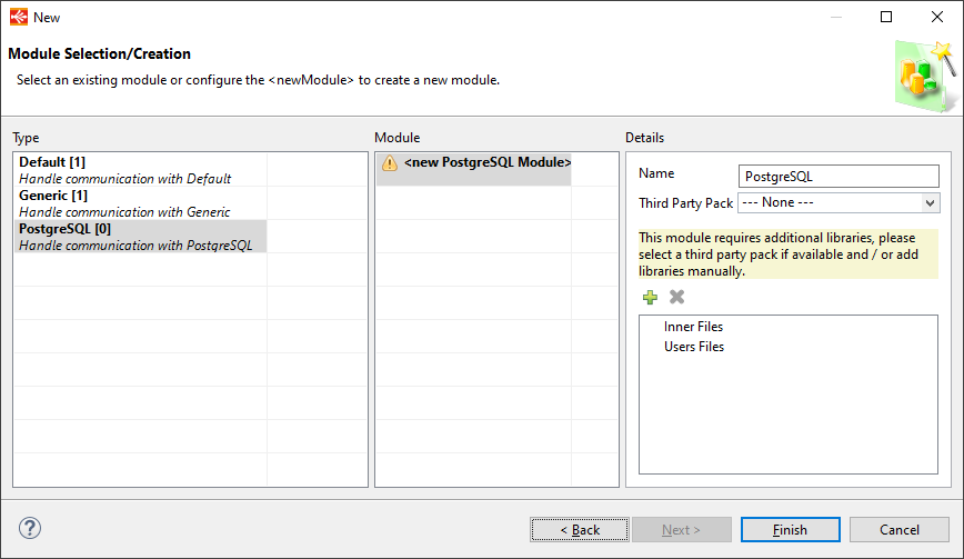
The Module Wizard is composed of three panes:
- Select a category on left pane
- Select an existing Module or create a new one on the middle pane
- Configure, if necessary, the selected Module on the right pane
- Then click on Finish
More detailed information about this Wizard can be found in the next section.
Modules Wizard
Introduction
Module Wizard will guide you to manage your Modules.
When possible, we provided all the necessary libraries for a given Module to communicate with a given technology.
When this is the case, the libraries are shipped within the Modules itself or through the selection of a third party pack.
When we cannot redistribute the libraries, for licenses purposes for instance, or when you want to use your own ones, you can also add them in Modules as explained further.
You can find below how to use the Module Wizard, what are the different Module statuses, and more.
Here is a quick overview of the Module Wizard:
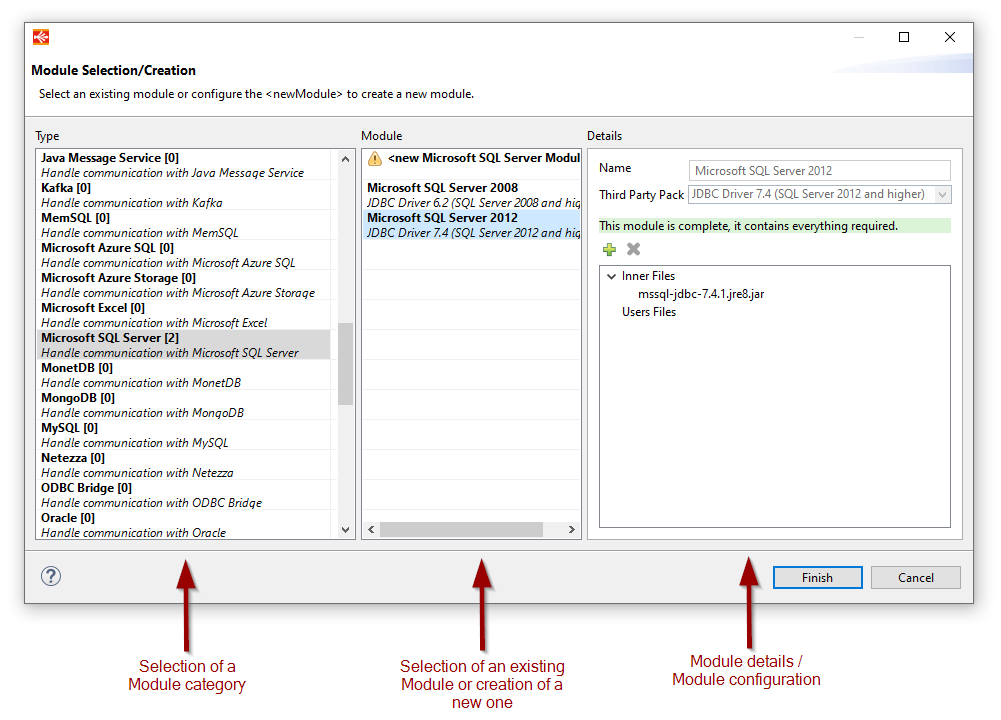
Modules Categories
On Module Wizard, the left pane contains all the categories of Modules, which represent all types of technologies provided in the current installation.
Depending from where you access the Module Wizard those categories will be filtered to only show the relevant ones for the current technology.
For instance, if you are creating a PostgreSQL Metadata, or if you are editing the Module used in a PostgreSQL Metadata, the Module Wizard will be filtered to only display the relevant categories which could be used to communicate with PostgreSQL.
Note that when installing additional Components in the Designer, this will fill this list with new categories.
Therefore, make sure you have installed the Components you need to have the category corresponding to your technology.
For instance, if you install Elasticsearch Component, Elasticsearch categories will appear in this left pane when applicable.
There are different types of categories:
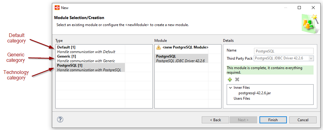
Default
The Default category contains only one Module called default which is an automatically created empty Module.
This Module is a fallback Module which is used automatically at execution when no Module is specified in Metadata.
This Module is not linked to any technology, you can put anything you want inside.
It can be used when migrating from previous versions where Modules did not exist for instance.
Generic
The Generic category is used to create Modules not linked to any particular technology, which can be used anywhere.
Generic category always appears in the Wizard as it can be used for any needs.
A Generic Module is an empty Module where you can put anything.
Technology
A technology category is used to create Modules for a given technology, each technology having its own.
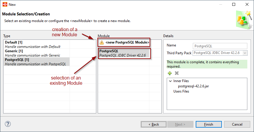
Modules List
On Module Wizard, the middle pane is listing all the user created Modules for the selected category.
From this pane, you will be able to select a previously created Module or create a new one using the <new [...] Module > entry.
For instance, if you created a PostgreSQL Module once, you can reuse it in all your PostgreSQL Metadata.
You don’t have to create a new one each time, the purpose of Modules is to be reusable when applicable.
When you are reusing the same Module in multiple Metadata, the only point to have in mind is that if you edit this Module this will impact all Metadata using it, which can be a good point if you want to manage more easily the libraries used for communication.
In this pane, you therefore have the choice to select an existing Module or to create a new one.
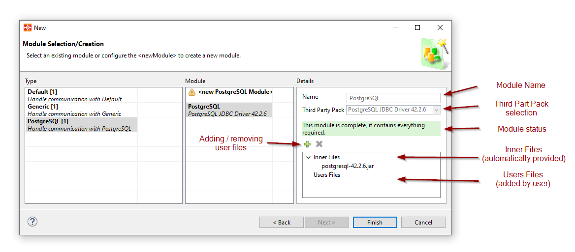
Modules Details
On Module Wizard, the right pane displays the details about the currently selected Module.
When creating a new Module, it allows to choose a name for it, a third pack if any, and add user files if needed.
When selecting an existing Module, it allows to see how the Module is configured, and to add additional user files if needed.
As a reminder, a Module is a set of libraries for communicating with a given technology.
The idea is therefore to provide in a Module the necessary libraries for communicating.
When possible, Stambia is already shipping and providing what is necessary for this, directly in the Module or through Third Party Packs.
Look closely to Module’s status to know if something has to be done.
Module Statues
| Color | Message | Description |
|---|---|---|
| Green | This module is complete, it contains everything required. | A Module with this status is ready to be used. It is considered as complete and contains all what is required. You can use it now without any additional operation. |
| Blue | This module may be complete, some additional libraries have already been added to this module from third party pack and / or from manual addition. | A Modules with this status may be complete and ready to use as is. Some additional libraries / files have already been added by selecting a Third Party Pack or by adding libraries manually, but the Designer does not have the possibility to know if this is enough for this type of Module. Refer to your product documentation to know if what you added / selected is enough. If it is, you can use this Module as is. |
| Yellow | This module requires additional libraries, please select a third party pack if available and / or add libraries manually. | A Module with this status is not ready to be used. It requires additional libraries to work. You can select a Third Party Pack if some are available to add third party libraries, or add your own libraries by looking at your product documentation to find what is required. It is mandatory to configure these additional libraries to be able to create the module. |
| Red | This module definition is not present in the current installation, you should install the related Component. | When this status appears on a Module, this means that the related Component with which it has been created is not installed in Designer. Install the related Component in the Designer and this status should disappear. This is typically the case where you are trying to use an existing Module created for a given technology which is not installed in the current Designer. For instance, you have an Elasticsearch Module, but Elasticsearch Component is not installed in the Designer. |
About Third Party Packs
Third Party Packs are optional set of additional libraries provided for a given type of Module.
When selecting a Third Party Pack, this will add the libraries contained in this pack in the ‹Inner Files› section of the Module.
Most of the time, selecting a Third Party Pack will be enough to complete Modules which requires additional libraries.
Why are they separated as packs and not directly provided in Inner Files?
Those set of libraries are separated as Third Party Packs to let you decide if you want to use those provided third party libraries or use your own ones.
For instance, you may have the choice between several versions of JDBC Drivers which work for several versions of databases servers, so you have the choice to use the one which suits the best your environment.
And you may also prefer to use your own libraries with your own versions which suits better your environment, so in this case you will not select a Third Party Pack and add manually your libraries instead.
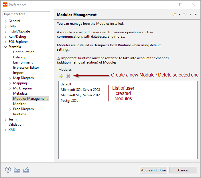
Modules Managers
Module Manager
You can manage all the Modules from the Modules Manager.
To access it, go to Utilities > Module Manager
From this section you can:
- Create a new Module by clicking on the plus button
- Delete the selected Module by clicking on the delete button
- Edit an existing Module by double clicking on its name
Metadata Module Manager
You want to control the Modules used in all your Metadata?
You want to assign a given Module in mass on all corresponding Metadata?
You can use for this the Module Metadata Manager.
To access it, go to Utilities > Metadata Module Manager
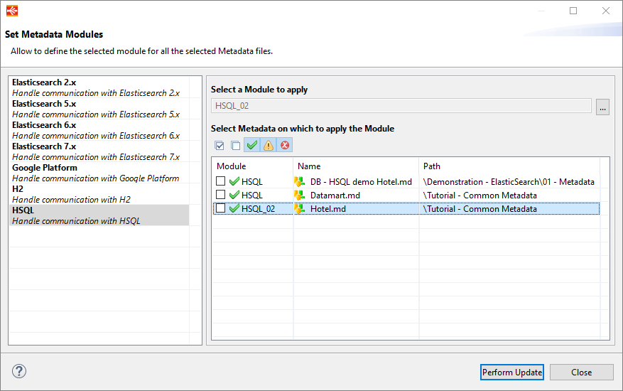
Start the wizard, then select a category of Module on the left.
You will then have the list of Metadata you have in your workspace which are applicable for the given category.
You can see for each Metadata the Module it is using.
If you want to assign a given Module, select the Module, check all the Metadata on which you want to apply this Module, and click on Perform Update.
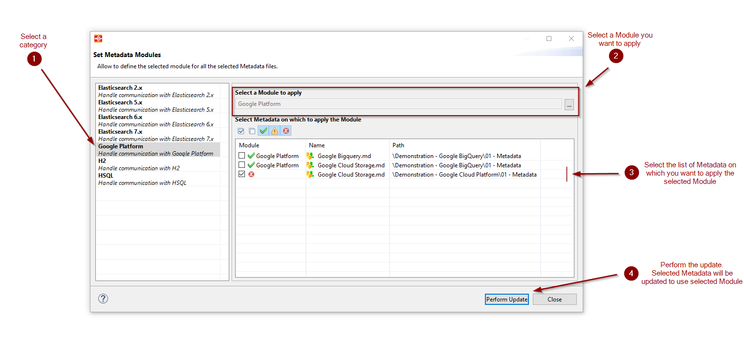
Note that when a Module already exists for a given category, it will be preselected in «Select a Module to apply» box.
You can of course select another one using the select button at the right of the box.
Note also that the categories on the left are filtered based on the Metadata you have in your workspace, it will only show categories for which you have Metadata in your Workspace. For instance, if you do not have PostgreSQL Metadata files on your workspace, you will not have PostgreSQL category on the left. This wizard is used only to assign Modules in mass in your existing Metadata. If you want to prepare Modules for technologies you haven’t created Metadata yet, prefer using the main Module Manager presented above.
Additional Modules Information
What is a Module, physically?
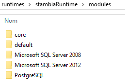
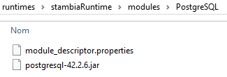
Physically, a Module is a folder containing all the libraries added inside and a descriptor file which is used to store some information about the Module.
You must NOT modify this descriptor file which is handled automatically by the Designer for managing the Module.
All the Modules are stored in a dedicated folder which defaults to the ‹modules› folder of the Runtime.
Folder containing modules
Example of Module
Module Behavior
Modules in Designer
The Designer can create, edit, delete and assign Modules in Metadata and Processes.
The Designer itself will only use Modules when needing to communicate with a technology, for instance when connecting to a database for reversing its structure, when connecting to a database to perform SQL queries in SQL Explorer, and more...
All the Modules managed by the Designer are managed inside the Modules folder specified in its startup settings, which defaults to Designer’s local Runtime ‹modules› folder in standard installation, for the local Runtime to benefit of the Modules at execution.
When developing Mappings and Processes, the Modules defined in Metadata will be generated in final delivery, so that the Runtime knows which Module should be used when executing the delivery.
Modules in Runtime
When starting, the Runtime will load all the Modules located in its ‹modules› folder when working with default settings.
When executing deliveries which are using Modules, the Runtime will try use the defined Modules when it needs it.
If the Module is not found in the current Runtime while executing, a convenient error will be thrown during the execution to inform the user the Runtime does not know this Module.
When this happens, make sure the Module exists in the given Runtime ‹modules› folder or, if you changed the default Modules location, in the location you defined. Make sure also the Runtime has been restarted since the Module has been added inside, as Modules are taken into account at Runtime’s startup.
When no Modules are defined in a delivery, which usually happens when no Module is defined in the Metadata which has been used to generate the delivery, the Runtime will at execution fallback to the Module called ‹default› which is the fallback Module in case no Module is specified. This can happen for instance when migrating from version previous to S20.0.0 in which the Module feature did not exist yet.
Modules for Runtime log database
When you are using another Runtime log database than default H2 log database, the Runtime will need the JDBC Driver corresponding to the database you use to be able to communicate with it.
The JDBC Driver must be put inside «default» Module.
Refer to Runtime’s Installation and Configuration Guide for further information.
Modules for Runtime scheduler
When you are using Runtime’s internal scheduler, if you configured it to use another database than default H2 database to store the schedules, the Runtime will need the JDBC Driver corresponding to the database you use to be able to communicate with it.
The JDBC Driver must be put inside «default» Module.
Refer to Runtime’s Installation and Configuration Guide for further information.
Externalizing Modules folder
As indicated previously in this documentation, Modules are managed by Designer and Runtime in a specific folder.
The default folder which is used can be changed if you want to put it at another location than default one.
Refer to Designer Installation and Configuration Guide and Runtime Installation and Configuration Guide for further information on how to accomplish this.
Modules limitations
Modules on Scripting
Modules can be used natively with the following scripting languages: Beanshell, Rhino, Nashorn, Javascript.
Modules are not fully supported yet on following scripting languages: Jython, Groovy.
Refer to the following article for further information.
Modules troubleshooting
When you try to create a Module, you don’t see the corresponding category on the left
When you try to select or create a Module, you don’t see the category corresponding to the technology you want to create a Module for.
For instance, when you try to create a Module for Elasticsearch, you don’t see Elasticsearch in Modules Categories.
If you are in this case, please double check the following items:
- Make sure the corresponding Component is installed in Designer. For instance, if you want to use Elasticsearch, make sure Elasticsearch Component is installed.
- Make sure you are trying to select / create a Module on the proper Metadata. The Module Wizard is filtered based on the technology from which you want to select / create a Module for. For instance, if you are on an Elasticsearch Metadata, you will not see the Modules for PostgreSQL database, this is normal. As a consequence, make sure you are on the correct Metadata.
- If you have already checked the two above points and you still have issues, do not hesitate to contact us so that we can help, and fix issues if needed.
Your Module seems OK in Designer but when you try to execute a Mapping / Process using it, the Runtime returns that the Module is not found / does not exist
You configured your Modules in the Designer, everything looks fine, but when you try to execute you have an error returned by the Runtime which says that the Module is not found / does not exist.
If you are in this case, please double check the following items:
- The Runtime is taking into account its Modules at startup, so if you are working with a Module which has been created after the Runtime was started, you have to restart your Runtime.
- Make sure the Runtime on which you are executing your Mapping / Process contains the Module you are trying to use. On a default installation, Modules are located under <Runtime installation folder>/modules. Therefore, double check that the Runtime you are executing your Mappings / Processes on have the corresponding Modules you want to use. Most notably if you are using another Runtime than the local one shipped within the Designer, or if you have changed the default location of Modules.
When executing a Mapping or a Process, you have «java.lang.ClassNotFoundException» or «java.lang.Exception: Unable to find class» exceptions
When you are executing a Mapping or a Process, you have exceptions similar to:
- java.lang.ClassNotFoundException
- java.lang.Exception: Unable to find class
When you have such exceptions, this means that when trying to execute your Mapping or Process, the Runtime needed to communicate with a given technology or to perform any operation, but the corresponding Java classes for this could not be found in the actual installation.
If you are in this case, please double check the following items:
- Have a look at the corresponding Metadata and check if a Module if specified in this Metadata
- If a Module is already specified, make sure that this Module contains all the additional libraries required (such as JDBC Driver, ...)
- If no Module is specified, you have two different solutions
- Define a Module containing everything required in this Metadata
- If you prefer not defining Modules and using the fallback «default» Module instead, make sure that the «default» Module contains all the additional libraries required (such as JDBC Driver, ...)
Working with Mappings
What is a Mapping?
Mappings  relate source and target Metadata, and allow moving and transforming data from several source datastores (files, tables, XML) to target datastores.
Designing a Mapping: Overall Process
The overall process to design a mapping follows the steps given below.
- Creating a New Mapping
- Adding the Targets and Sources
- Linking datastores
- Joining the Sources
- Mapping the Target Columns
- Filtering the Sources
- Staging the Sources
Creating a New Mapping
To create a new mapping:
- Click on the New Mapping button in the Project Explorer toolbar. The New Map Diagram wizard opens.
- Select the parent folder or project for your new resource.
- Enter a File Name and then click Finish. The mapping file is created and the editor for this file opens.
Adding the Targets and Sources
To add the source and target datastores:
- In the Project Explorer, expand the metadata file containing the datastore (table, file, XML file) that you want to integrate.
- Drag and drop the datastores into which data will be loaded (the targets) from the Project Explorer into the mapping editor.
- Drag and drop the datastores from which data will be extracted (the sources) from the Project Explorer into the mapping editor.
For each datastore that has been added:
- Select this datastore.
- In the properties view, set the following properties:
- Alias: Alias used in the expressions when referring to this datastore. It defaults to the datastore’s name.
- Use CDC: Check this box to enable consumption of changed data from a source datastore, captured via the CDC feature.
- Enable Rejects: Check this box to enable rejects management on a target datastore. When this option is selected, rows in the data flow not meeting the target table’s constraints are isolated into the rejects instead of causing a possible Runtime failure.
- Update Key Provider:select the source of the key : manual definition or an existing constraint from the metadata.
- Tag: Add a tag to the table. Tags are used in certain process templates.
- Description: Free form text.
- In the Advanced properties section, the Order defines the order of a source datastore in the FROM clause generated when loading a target.
- In the Advanced properties section, the Integration Sequence specifies the order in which tables without any mutual dependencies must be loaded.
Press CTRL+S to save the mapping.
Linking datastores
To create a link between 2 datastores:
- Select a column from a source datastore in the mapping diagram.
- While keeping the mouse button pressed, drag this column onto another source column in the mapping diagram.
- Release the mouse button. You will be prompted to select the type of link to create:
- Join: a new join will link the 2 datastores
- Map: a source-target relationship will be created between the two columns and their datastores
Note: You will be prompted to select the type of link only if Stambia Designer detects that both kind of links can be created. Otherwise the accurate type of link will be automatically created.
Note: When creating a source-target link between the datastores, blocks representing the load and integration process templates are automatically added to the upper part of the target datastore.
Note: When linking a source datastore to a target, the columns from the source are automatically mapped to the target datastore columns using column name matching.
Hint: If a join already exists between two datastores, drag-and-dropping a column between these datastores adds it to the existing join expression. If you want to create a new Join between those datastores, hold the CTRL key pressed while dropping the column
Defining a Join between Sources
When a join has been created:
- In the Expression Editor view, edit the code of the join. You can lock the expression editor and drag columns from the diagram into the expression editor. See the Mapping, Filter and Join Expressions section for more information about mapping expressions.
- Select the join in the mapping diagram.
- In the Properties view, set the following Standard Properties:
- Enable: Enables or disables the join.
- Set the join type by selecting either Join Type to Inner, Full or Cross or by selecting the Left Part or Right Part to perform a left outer or right outer join. See Join (SQL) for a definition of the join types.
- Set the Execution Location. The join may be executed within the source system (when joining two datastores in the same data server) or in the staging area.
- Description: Free form text.
- In the Properties view, optionally set the following Advanced Properties:
- Join Type: Explicit uses the ISO Syntax (join in the FROM clause), Implicit places the join in the WHERE clause, and Default takes the default type defined for the technology. This latter option is preferred for non-inner joins
- Order: Defines the order of the join when using the Explicit Join type.
- Press CTRL+S to save the mapping.
Warning: Be cautious when using Cross and Full joins as they may lead to a multiplication of rows and performance issues.
Note: When a Join is created between two datastores a blue area appears representing a set of datastores that are Joined together. This area is called a dataset.
Understanding conditional Joins
A conditional Join allows to activate a dataset and its corresponding join only if the driving dataset is used.
To define a conditional Join:
- Select the join
- In the Properties view, open the Advanced Properties
- Set the Activate property:
- Always: The join is not conditional and will always be executed
- With datastore's dataset: The conditional join will be activated only if the dataset containing the datastore is used.
Note: Conditional joins can be particularly useful to mutualize loads inside a Mapping.
Mapping the Target Columns
The target columns must be mapped with expressions using source columns. These expressions define which source columns contribute to loading data into the target columns.
When a map expression has been defined on a target column:
- Select the target column.
- In the Properties view, set the following Standard Properties:
- Enable: Enables or disables the mapping.
- Set the Execution Location. The mapping may be executed within the source system, in the staging area or in the target itself (while inserting data into the target).
- Use as Key: Check this option if this column must be used as part of the unique key for this mapping. Several columns participate to the unique key in the mapping. These may be the columns from one of the target table’s unique keys, or different columns. This unique key is used in the context of this mapping to identify records uniquely for reject management and target records update purposes.
- Enable Insert: Enable inserting data with this mapping.
- Enable Update: Enable updating data with this mapping.
- Aggregate: Indicates that this column contains an aggregate expression. Other (non-aggregated) columns are added in the GROUP BY clause of the queries.
- Tag: Add a tag to the mapping. Tags are used in certain process templates.
- Description: Free form text.
- Press CTRL+S to save the mapping.
Understanding Column Icons
Source and target columns have an icon that contains the first letter of their datatype. This icon appears in grey when the source column is not used in the mapping or when the target column is not mapped
In addition, target columns are tagged with icons to identify their key properties. The various icons and their meaning are listed in the following table.
| Icon | Meaning |
|---|---|
 |
The yellow key indicates that the column is part of the key. The white star in the upper left corner indicates that the column is not nullable. If reject management is activated, rows with null values for this column are rejected. The letter represents the column data type (I: Integer, V: Varchar, etc.) |
 |
The star in the upper right corner means that the column is not nullable and Stambia checks the null values for this column. |
 |
The cross in the upper right corner means that the column is not nullable but Stambia does not check the null values for this column. |
 |
No sign in the upper right corner means that the column is nullable and Stambia does not check the null values for this column. |
 |
The plus sign in the upper right corner means that the column is nullable but Stambia checks the null values for this column. |
 |
This expression runs in the source. |
 |
This expression runs in the staging area. |
 |
This expression runs in the target. |
 |
These four letters have the following meaning when they appear:
|
Using Computed Fields
Computed fields are virtual fields, which are calculated on the fly during execution. They are only available during execution and are not stored.
To create a computed field on a mapping:
- Right-click on a column and select Create ComputedField
- A name for the container of the computed fields will be asked for the first created on the datastore.
- Finally, you can change the expression of the computed field to your needs.
Info Computed fields can be created only on objects having transformation capacities (RDBMS mostly, with SQL syntax)
Tip It is possible to create a computed field from an other computed field too. Usefull to chain transformations or operations.
Filtering the Sources
Creating a filter
The data from the various source datastores may be filtered.
To create a filter:
- Select a column from a source datastore in the mapping diagram.
- While keeping the mouse button pressed, drag this column into the mapping diagram.
- Release the mouse button.
- A menu appears to choose what you want to do with this field, choose Create a Filter
- A filter is created and appears in the diagram.
- In the Expression Editor view, edit the code of the filter. You can lock the expression editor and drag columns from the diagram into the expression editor. See the Mapping, Filter and Join Expressions section for more information about filter expressions.
- Select the filter in the mapping diagram.
- In the Properties view, set the following Standard Properties:
- Enable: Enables or disables the filter.
- Aggregate: Check this option if this filter is an aggregate and must produce a HAVING clause.
- Set the Execution Location. The join may be executed within the source system or in the staging area.
- Description: Free form text.
- Press CTRL+S to save the mapping.
Tip: It may be preferable to position the filters on the source to reduce the volume of data transferred from the source data server.
Info: To create a filter that must be executed only when a specific conditional join is activated, drag and drop the source column onto the conditional join itself and update the Expression.
Target filters
A filter can be configured to be activated only for one target.
Right-click on the filter and select Activate > For [...]
Staging the Sources
What is a Stage?
A Stage is a temporary location where you will be able to mutualize expressions transformations, perform unions and joins of multiple sources, and more...
Creating a Stage
To create a new stage in a Mapping, drag and drop one or multiple source fields from a datastore into the editor:
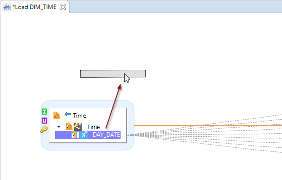
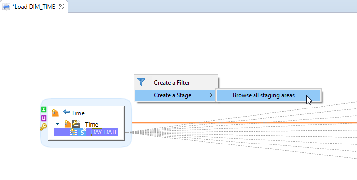
A menu will open in which you have to select Create a Stage > Browse all staging areas:
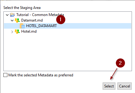
A dialog box will open to choose a Metadata node on which to create the Stage
This represents a database schema on which the stage operations will be performed, and in which temporary stage objects will be created when necessary.
Defining stage properties
If you select the created stage, you can define some addition properties, such as changing its name to a more convenient name.
- In the Properties view, you can change the following properties:
- Alias: Alias used in the expressions when referring to this stage, which can be useful to define a convenient name.
- Tag: Add a tag to the stage. Tags are used in certain process templates.
- Description: Free form text to specify some description.
- In the Advanced properties section, the Integration Sequence specifies the order in which tables and stages without any mutual dependencies must be loaded.
Adding fields to the stage
- Select the stage.
- Click on the
 button to add a new field to the Stage.
 - In the Properties view, set the following properties:
- Alias: Alias used in the expressions when referring to this field.
- Enable: Enables or disables the mapping.
- Aggregate: Indicates that this column contains an aggregate expression. Other (non-aggregated) columns are added in the GROUP BY clause of the queries.
- Tag: Add a tag to the mapping. Tags are used in certain process templates.
- Description: Free form text.
Press CTRL+S to save the mapping.
Tip: Note that you can also create a Stage by drag-and-dropping the schema directly from Project Explorer View inside the Mapping editor.
Info: you can also add fields to the stage by dragging a source field and dropping it on the stage.
Adding sets to a stage
To create a new set:
- Select the stage.
- Click on the
 button to add a new set to the Stage.
 - In the Properties view, set the following properties:
- Alias: Alias used in the expressions when referring to this set.
- Description: Free form text.
- In the Expression Editor view, set the operators to use between the sets:
- Each set can be referred to as
[nameOfTheSet] - For example:
([A] union [B]) minus [C]
- Each set can be referred to as
- Select the set and map the fields in this set
Press CTRL+S to save the mapping.
Preferred staging area locations
To ease the creation of Stages, you can define preferred staging area locations.
They will appear in the context menu when trying to create a Stage.
This can be useful if you are often using the same Metadata as staging area to be able to use it in a few clicks.
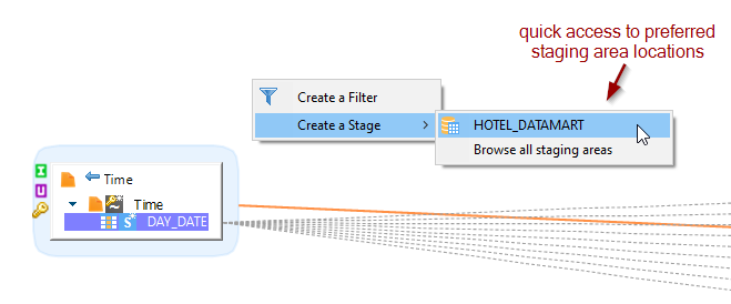
You can define a staging area location as preferred from the Browse all staging areas popup by checking the corresponding box when creating a Stage

Note that preferred staging are locations can be managed from Designer’s preferences also, from the following menu: Windows > Preferences > Stambia > Mapping > Staging Area
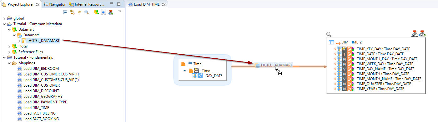
Creation of a stage on the fly
When you drop a schema from Project Explorer View on an already existing link between sources and a target, this will automatically create a stage which will be initialized from existing mapping expressions!
For this drag and drop a schema directly on a link between a source and target dataset.
You’ll have a menu to help you decide which behavior to choose to create the fields of the stage.
Should they be created alike the source or alike the target?
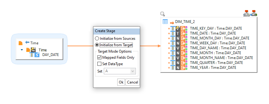
Define what you prefer and press OK.
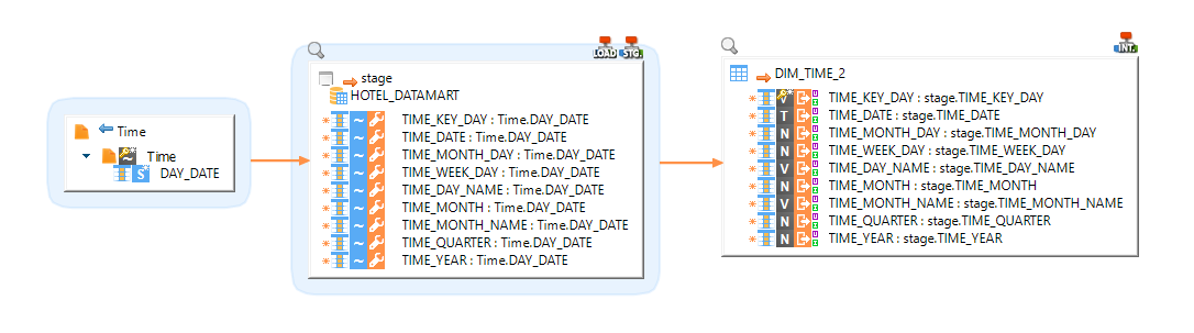
A stage will be automatically created and initialized between your source and target datasets.
Mapping, Filter and Join Expressions
For a mapping, filter or join, you specify an expression in the expression editor. These expressions are also referred to as the code of the mapping, filter or join.
The mapping, join or filter code can include any expression suitable for the engine that will process this mapping, filter or join. This engine is either the engine containing the source or target datastore, or the engine containing the staging area schema. You select the engine when choosing the Execution Location of the mapping, filter or join. This engine is typically a database engine. In this context, expressions are SQL expressions valid for the database engine. Literal values, column names, database functions and operators can be used in such expressions.
Examples of valid filter expressions:
CUSTOMER_COUNTRY LIKE 'USA'COUNTRY_CODE IN ('USA', 'CAN', 'MEX') AND UCASE(REGION_TYPE) = 'SALES'
Examples of valid join expressions:
CUSTOMER.COUNTRY_ID = COUNTRY.COUNTRY_IDUCASE(CUSTOMER.COUNTRYID) = GEOGRAPHY.COUNTRY_ID AND UCASE(CUSTOMER.REGIONID) = GEOGRAPHY.REGION_ID
Examples of valid mapping expressions:
- For the CUSTOMER_NAME field:
SRC.FIRST_NAME || ' ' || SRC.LAST_NAME - For the SALES_NUMBER aggregate field:
SUM(ORDERLINE.AMOUNT) - For an OWNER field:
'ADMIN'to set a constant value to this field.
Tip: When editing a Join or a Filter, think of it as a conditional expression from the WHERE clause. When editing a mapping, think of one expression in the column list of a SELECT statement.
Restrictions
- It is not possible to use a Stage as a source for another Stage if they are on different connections.
- A datastore can be joined or else mapped with another datastore, but not both actions at the same time.
Working with Processes
Processes  define organized sequences of Actions executed at run-time on the IT systems.
Processes are organized using Sub-processes, which are themselves composed of actions, sub-processes or References to other processes.
Creating a Process
Creating a new Process
To create a new process:
- Click on the New Process button in the Project Explorer toolbar. The New Process Diagram wizard opens.
- Select the parent folder of project for your new resource.
- Enter a File Name and then click Finish. The process file is created and the editor for this file opens.
- Press CTRL+S to save the process.
Adding a Mapping
To add a mapping to a process:
- Drag and drop first the mapping from the Project Explorer into the process editor. This mapping is added as a reference in the current process.
Adding an Action
To add an action:
- In the Palette, select the action that you want to add to the process. You can expand the accordions in the palette to access the appropriate action.
- Click in the process diagram. A block representing your action appears in the diagram.
- Right-Click this action and then select Show Properties View.
- In the Properties View, set the following values
- In the Standard section:
- Name: Name of the action. Use a naming convention for the action names as they are used in the variable path.
- Enable: Select this option to have this action enabled. Disabled actions are not executed or generated for execution.
- Error Accepted: Select this option to have this action complete with a Success status, even if it has failed.
- In Standard section, you also have a list of Parameters, each action having its own set of parameters.
- The mandatory parameters appear as editable fields. Enter values for these parameters.
- The optional parameters (possibly having a default value) appear as non-editable fields. Click on the field name to unlock the field value and then enter/select a value for these fields.
- In the Description section:
- Description: Detailed description of the action.
- In the Advanced section
- Dynamic Name: Dynamic Name for this action. This name may change at run-time and is available through the CORE_DYNAMIC_NAME variable.
- Is Begin Action: Select this option to declare this action explicitly as a startup action.
- Semaphore name: This option allows to define a name to synchronize actions between them when several actions are executed at the same time.
- When an action is executed, it checks if the semaphore name defined is not currently in use by another action, and if it is the case, it will wait for the other action to finish before executing.
- When multiple actions are defined with the same semaphore name, they will therefore be automatically executed sequentially even if they are started in parallel in the Process, but the order of execution is not predictable.
- Note that you should prefer, when possible, ordering and linking actions properly in Processes, by linking them sequentially when they cannot be parallelized.
- In the Meta-Inf section define log additional messages from a process to the log files, console, and runtime log database. Each <userLog> element has the following properties :
- path attribute: the Name of the message (and optionnally the path to the process step it should be attached to) - usefull in analytics
- trigger attribute: when the message should be logged, beforeExecution or afterExecution of the action
- info element: defines the message content
- logger element(s): specifies which logger will receive the message – by default you can use:
- userConsole: logs into the Runtime’s standard output
- mainConsole: same as userConsole, prefixed with date/time
- stambiaLog: logs into the Runtime’s log database
- In the Standard section:
Here is a sample userLog Meta-Inf :
<userLog path="../START/ScriptingWatcher" trigger="beforeExecution">
         <info>Before Scripting: param=${~/param}$</info>
         <logger>stambiaLog</logger>
         <logger>mainConsole</logger>
    </userLog>
    <userLog path="../START/ScriptingWatcher" trigger="afterExecution">
         <info>After Scripting: param=${~/param}$</info>
         <logger>stambiaLog</logger>
         <logger>mainConsole</logger>
    </userLog>
Press CTRL+S to save the process.
Adding a Sub-Process
To add a sub-process:
- In the Palette, select the Process tool in the Component accordion.
- Click in the process diagram. A block representing your sub-process appears in the diagram.
- The focus is on this sub-process. Type in a name for this process and then press ENTER.
- A new editor opens to edit this sub-process.
Note: You can nest sub-processes within sub-processes.
Referencing another Process
For modular development, you can use another process within your process as a reference.
To reference another process:
- Drag and drop first the process that you want to reference from the Project Explorer into the process editor. This process is added as a reference in the current process.
- Select the referenced process step in the process diagram, right-click and then select Show Properties View.
- In the Parameters section, set the action’s parameters. Each process has its own set of parameters.
- Press CTRL+S to save the process.
Breadcrumb Trail
At the top of the process, a Breadcrumb Trail is displayed to navigate in the sub-processes.
By default, only the main process editor can be edited (main process and sub-processes created inside).
All process links (Mappings, reference to other processes, ...) are read only, to prevent modification of other processes by error.
To enable the edition:
- Right click on a sub-process on the Breadcrumb Trail and click on Enable Edition. This will enable the edition directly inside this process.
- Right click on a sub-process on the Breadcrumb Trail and click on Open Editor. This will open a new editor for the selected sub-process.
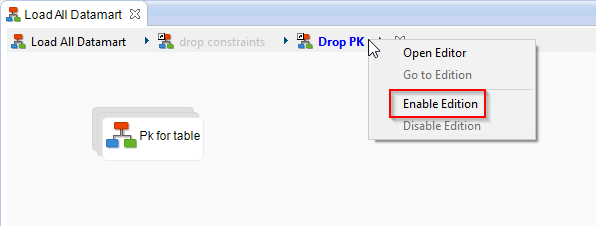
Execution Flow
Steps Features
At a step level, a number of features impact the execution flow. These include Conditional Generation, Step Repetition and Startup Steps.
Conditional Generation
It is possible to make conditional the generation of given steps in a process.
For example, you can generate only certain steps in the process depending on the startup parameters of the process
To make a step’s generation conditional:
- Select the step in the process diagram, right-click and then select Show Properties View.
- In the Generation section, optionally set the following options:
- Generation Condition: Condition to generate the action code. If it is left empty, the action will be executed regardless of the condition. See Using Scripts in Conditions for more information.
- Press CTRL+S to save the process.
Step Repetition
Repetition allows you to generate a step several times to run in parallel or sequence. This repetition can be performed in parallel or sequence, and is done using the result of an XPath Query.
To enable step repetition:
- Select the step in the process diagram, right-click and then select Show Properties View.
- In the Generation section of an action or process:
- Provide an XPath Query. The action will be generated for each value returned by this query.
- Provide a Variable Name. This variable will contain each of the values returned by the query and pass them to the action. You can use this variable name in the action code.
- Specify whether this repetition must be Sequential or Parallel.
- In the Generation section of an action or process:
- Press CTRL+S to save the process.
Note: This repetition applies to the generation. It can be used for example to create one step for each table in a model.
Startup Steps
By default, all the steps with no incoming links are considered as startup steps. As a consequence, a process can start with several simultaneous steps.
In certain cases, (for example in the case of a process that is a loop) there is no step that can be identified as a startup step. In these cases, you must explicitly indicate the startup steps by checking the Is Begin Action option for these steps.
Classic Links
A classic link sequences two steps.
To add a classic link:
- In the Palette, select the OK Link tool in the Link accordion.
- Select a first step in the package diagram. While keeping the mouse button pressed, move the cursor onto another step and then release it. A link appears between the two steps.
- Right-Click this link and then select Show Properties View.
- In the link properties, set the following options:
- Generation Type: Define whether this link should be generated if the first step is Successful, Unsuccessful, or always (Anyway).
- Execution Type: Define whether this link should be triggered if the first step is Successful, Unsuccessful, or always (Anyway).
- Triggering Behavior: Define whether this link is Mandatory, Inhibitory or Not Mandatory for second step to run.
- Optionally set Generation and Execution Conditions for this link. See Using Scripts in Conditions for more information.
At execution time:
- When the first steps completes, depending on its completion status, the Generation Type and the Generation Condition, the link is created or not.
- Then the link is triggered depending on the first step’s completion status, the Execution Type and the Execution Condition.
- Finally, the second step runs depending on all the incoming links' Triggering Behavior value. For example:
- A step with two incoming Not Mandatory links (and no other) can start if one or the other link is triggered.
- A step with two incoming Mandatory links (and no other) can start only if both links are triggered.
- A step with one incoming Inhibitory link (and many others) will not run if this link is triggered.
Note: A default link is always generated (Generation Type=Anyway), triggered only if the first step is successful (Execution type=Successful) and Mandatory for the second step to execute.
Note: Links with conditions appear as dotted links.
Process Development
Process Parameters
A parameter is used to parameterize a process' behavior. The value of this parameter is passed when starting the process or when using it as a referenced process in another one.
To create a process parameter:
- In the Palette, select the Parameter tool in the Component accordion.
- Click in the process diagram. A block representing your parameter appears in the diagram.
- Right-Click this block and then select Show Properties View.
- In the Properties views, set the following values in the Core section:
- Name: Name of the parameter. Use a naming convention for these names since they are used in the variable path.
- Type: Type of the parameter.
- Value: Default Value for this parameter.
- Press CTRL+S to save the parameter.
To use a process parameter, refer to it as a variable in your code, using the ${<parameter_name>}$ syntax.
Direct Bind Links
The direct bind link is a specific type of link that allows you to run a target action once for each record returned by the source action.
For each iteration, the target action has access to the bind variables sent by the source, which can be used through the bind syntax::{column_name}:.
By default, the execution of a bind link stops as soon as one of the iteration fails.
The corresponding error is then thrown and the target action is put in error.
If needed, you can change this behavior to let all the iterations executes, even when an error occurs in one of them.
To accomplish this, simply uncheck the ‹Stop Bind On Error› parameter in the advanced tab of the target action.
Note: This parameter can only be changed on Actions targeted by a bind. Moreover, when multiple errors occur during the bind iterations, it is the first encountered that is thrown on the action at the end of the execution.
Warning: The ‹Stop Bind on Error› functionality requires Stambia DI Runtime S17.2.16 or higher.
Example with a SQL Operation action:
- The first action is a SELECT SQL Operation.
- The second action can be any action, including an INSERT/UPDATE/DELETE SQL Operation. This second action is repeated for each record returned by the select operation.
- The columns of the records returned by the select operation can be used in the second action using the bind syntax:
:{column_name}:.
For example, the first action performs the following SELECT query:
SELECT CUST_NAME, CUST_COUNTRY, CUST_CODE FROM CUSTOMER
The second action can generate a file with the following parameter
- TXT_WRITE_FILENAME:
/cust/docs/customer_:{CUST_CODE}:_content.txt
One file is written per customer returned by the select statement, named after the customer code (CUST_CODE).
Link Metadata to Actions
It is possible to link metadata to actions and processes.
A link allows you to use metadata information in actions without having to hardcode it. Instead, references to the metadata information are used in the actions.
When linking metadata to action, these metadata references are converted to metadata information at generation time, and the action code remains generic. If a link is made to another metadata file, or if the metadata is modified, then the action will use the new metadata information.
Note: Metadata Linking is used frequently to use within processes the connection information and other structural information (table names, list of columns, etc.) stored in metadata files.
Linking Metadata to a Process/Action
To link metadata to an action:
- Open the process that you want to modify.
- In the Project Explorer view, select the metadata that you want to link. For example a data store or a data server.
- Drag and drop the metadata onto the action in the diagram. It is added as a Metadata Link on the action element.
- Select this metadata link, right-click and then select Show Properties View.
- In the properties view, set the following parameters:
- Name: Name of the Metadata Link. This name is used to access the content in the metadata.
- Description: Description for the metadata link.
- Visibility: Define whether the link is visible for this current action or for the parent of the action too.
- Press CTRL+S to save the process.
Using the Metadata Connection
By linking actions (or processes containing actions) to a data server or schema defined in metadata file, you automatically use this data server or schema for the action. If the action required a SQL Connection, the SQL connection of the linked metadata is automatically used.
Using Metadata Specific Information
Through the metadata link, you can access specific information within the metadata. This information is accessed using an XPath query.
To use a value in a metadata link, in the code or any text field of the action, specify the XPath to the value.
Note that:
- You should use the Name set when defining the metadata link as a variable in the XPath expression.
- The XPath expression must be surrounded with
%x{...}x%in order to be interpreted accordingly and replaced by its value at run-time.
For example, a metadata link to a dataserver was named Local_XE. It is possible to use the following XPath to retrieve the JDBC URL of this data server in the action:
%x{ $Local_XE/tech:jdbcUrl() }x%
Working with Scripting
What is Scripting?
Scripting is a feature which helps you to customize the behavior of your processes.
The idea is to be able to develop your own scripts on your preferred language and execute them in Stambia.
You can use scripting in various locations in Stambia.
Through Process Actions
In which you will enter you code directly on the action, which will execute it.
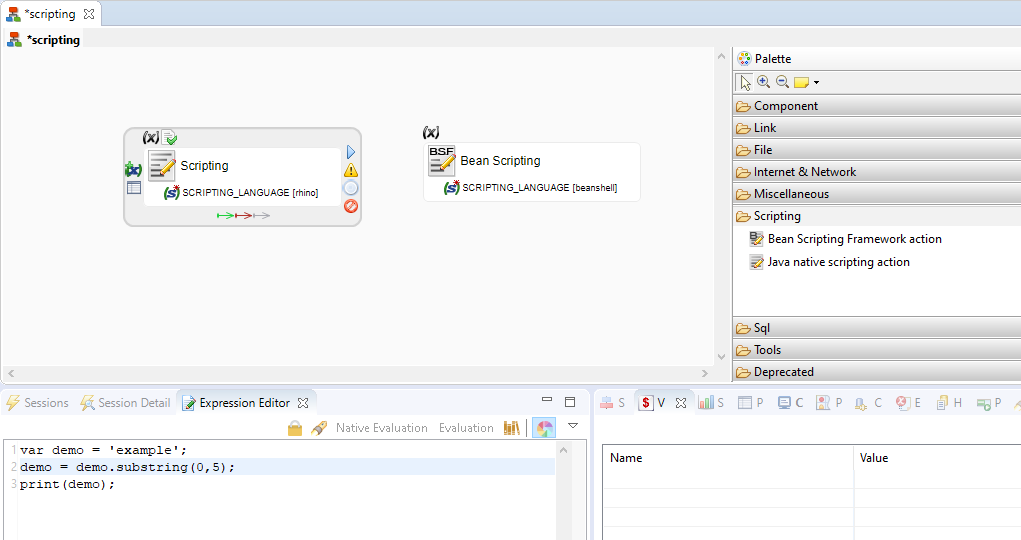
In all the textual fields
Which means conditions, texts, parameters, etc... with the %e(<language>){<script>}e(<language>)% syntax.
In this context, the script is interpreted and the result of the script execution (return code) replaces the script in the field.
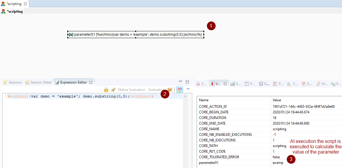
Scripting Language
It is possible to specify the scripting language when using scripting.
In addition to JavaScript (Rhino), Groovy, Python (Jython) and Beanshell are supported.
When using scripting in a scripting Process Action, simply define the script to be used on the Scripting Language Parameter of the action.
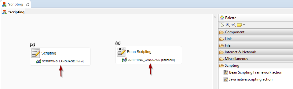
When using scripting in a textual field, you can define the language using the following syntax: %e(<language>){...}e(<language>)%
For example:
%e(rhino){...}e(rhino)%%e(groovy){...}e(groovy)%%e(jython){...}e(jython)%
Using external libraries
If you want to use in your scripts classes which are in additional libraries which are not shipped within the Runtime, you must add your libraries in a Module and use the Module on the scripting Process Action.
You’ll then be able to use the classes of the libraries contained in this Module.
Refer to Modules documentation for further information about Modules.
Using a Module is supported only when executing scripts in scripting Process actions, not when using the syntax to use scripts in other fields.
Using Session Variables
Stambia stores information about each action and process. This information is available as session variables.
These variables can be used in the code/text of an action, in its parameters, and in its metadata. Variables can also be used in scripts, for example in conditions.
The syntax to use a variable is ${variable_path}$ where variable_path is the path to the variable.
A variable belongs to an action or a process. This action or process may be contained in another process, and so on.
This organization is similar to a file system organization, with the main process at the root. You can access a variable with an absolute or relative path, depending on the location from which you request this variable.
For example if a process LOAD_DW contains a sub-process LOAD_DIMENSION which includes a sub-process LOAD_TIME which includes an action called WRITE_FILE, then the return code of this action is the following variable:
${LOAD_DW/LOAD_DIMENSION/LOAD_TIME/WRITE_FILE/CORE_RET_CODE}$
If you use this variable from the READ_FILE process within the LOAD_TIME sub-process, then the relative path is:
${../WRITE_FILE/CORE_RET_CODE}$
To use the return code of the current action, you can use:
${./CORE_RET_CODE}$
If the parent process' name is unknown, you can use the ~/ syntax:
${~/WRITE_FILE/CORE_RET_CODE}$
In the previous case, ~/ is replaced with LOAD_DW/LOAD_DIMENSION/LOAD_TIME/
Using Scripts in Conditions
Conditions may define whether:
- A link is generated or triggered (Link’s Generation and Execution Conditions)
- A step is generated (Step’s Generation Condition)
A condition:
- is a script that returns a Boolean value.
- may use session variables using the
${<variable>}$syntax.
The default language used for the conditions is JavaScript (Rhino implementation) and the interpreter adds the %e(rhino){...}e(rhino)% around the code in conditions.
Example of a condition: ${./AUTOMATION/CORE_NB_EXECUTIONS}$==1. The CORE_NB_EXECUTION variable (number of executions) for the AUTOMATION step should be equal to 1 for this condition to be true.
When a script is more complex than a simple expression, the context variable __ctx__.retvalue can be used to return the Boolean value from the script to the condition, as shown below.
%e(rhino){
/* Retrieves a session variable value */
myVarValue = '${~/MYVARIABLE}$';
if (myVarValue.substring(0,1).equals('R')) {
/* Returns true */
	__ctx__.retValue = "true";
}
else {
/* Returns false */
	__ctx__.retValue = "false";
	}
}e(rhino)%
Note that this script also shows on line #3 the retrieval of the value for session variable MYVARIABLE.
Using the Scripting Context
When a script is interpreted, an object is passed to this script to provide access to the Runtime Engine features. This Context object is accessed using __ctx___.
This object provides a list of methods for manipulating variables and values as well as a return value used for code substitution and condition evaluation.
The following sections describe the various elements available with this object.
retValue Variable
The scripting context provides the retValue (__ctx__.retValue) variable.
This String variable is used to:
- return to the condition interpreter a Boolean value.
- return a string that replaces the script during code generation.
publishVariable Method
public void publishVariable(String name, String value) {}
public void publishVariable(String name, String value, String type) {}
This method is used to publish a session variable, and takes the following parameters:
- name: variable path.
- value: value of the variable.
- type: type of the variable. The default value is String. The possible values are: Float, Integer, Long, Boolean and String.
Example: Publish a string variable called INCREMENTAL_MODE with value ACTIVE on the parent element of the current action.
__ctx__.publishVariable("../INCREMENTAL_MODE","ACTIVE");
sumVariable, averageVariable, countVariable, minVariable and maxVariable Methods
public String sumVariable(String name) {}
public String sumVariable(String name, String startingPath) {}
public String averageVariable(String name) {}
public String averageVariable(String name, String startingPath) {}
public String countVariable(String name) {}
public String countVariable(String name, String startingPath) {}
public String minVariable(String name) {}
public String minVariable(String name, String startingPath) {}
public String maxVariable(String name) {}
public String maxVariable(String name, String startingPath) {}
These methods return the aggregated values for a variable. This aggregate is either a Sum, Average, Count, Min or Max.
The aggregate is performed within a given path.
This method takes the following parameters:
- name: Name of the variable
- startingPath: Path into which the variable values must be aggregated. If this parameter is omitted, the values are aggregated for the entire Session.
Example: Aggregate all the numbers of rows processed for LOAD_DIMENSION process and all its sub-processes/actions.
__ctx__.sumVariable("SQL_NB_ROWS","../LOAD_DIMENSION");
getCurrentBindIteration Method
public long getCurrentBindIteration() {}
This method returns the current bind iteration number. It takes no input parameter. See Direct Bind Links for more information about bind iterations.
getVariableValue method
public String getVariableValue(String path) {}
This method returns the value of a session variable, and takes the following parameter:
- path: Variable path.
Example: Retrieve the value of the CORE_SESSION_ID variable.
__ctx__.getVariableValue("/CORE_SESSION_ID");
getVariableCumulativeValue Method
public Object getVariableCumulativeValue(String name) {}
When an action iterates due to a bind or a loop, the variables store their value for the last iteration.
In addition, numerical values contain a cumulated value which can be retrieved.
This method takes the following parameters:
- Name: Path of the numerical variable.
getVariableTreeByName Method
public Map<String, IVariable> getVariableTreeByName(String name) {}
public Map<String, IVariable> getVariableTreeByName(String name, String startingPath) {}
public Map<String, IVariable> getVariableTreeByName(String name, boolean withErrors) {}
public Map<String, IVariable> getVariableTreeByName(String name, String startingPath, boolean withErrors)
This method returns a treeMap object containing the variables corresponding to certain criteria. It takes the following parameters:
- name: Name of the published variable.
- startingPath: Path from which the variable must be searched (The default value is
~/) - withErrors: Boolean value. If set to true, only the variables from steps in error are retrieved. It is set to false by default.
The returned Java Map object has the name of the action as the key and its value is a variable object with the following methods.
public Object getCumulativeValue(); // variable cumulated value (numbers only)
public String getShortName(); // variable name.
public String getName(); // variable name with path.
public String getActionName(); // action name with path.
public String getType(); // variable type.
public String getValue(); // variable value.
Usage example in Groovy: Retrieve the stack trace for all the steps in error.
%e(groovy){
def a = ""
def tree = __ctx__.getVariableTreeByName("CORE_STACK_TRACE","~/",true)
if (tree.size() != 0) {
	def es=tree.entrySet()
	es.each{
	  	a = a+ "-- ACTION --> " + it.key + "\n"
	  	a = a+ it.value.getValue() +"\n\n"
	}
	__ctx__.retValue = a
}
}e(groovy)%
Same example in JavaScript (Rhino):
%e(rhino){
importPackage(java.util);
a = "";
tree = __ctx__.getVariableTreeByName("CORE_STACK_TRACE","~/",true);
if (tree.size() != 0) {
	for (i= tree.keySet().iterator() ; i.hasNext() ; ){
	    action = i.next();
	    maVar = tree.get(action);
	  	a = a+ "-- ACTION --> " + action + "\n";
	  	a = a+ maVar.getValue() +"\n\n";
	}
	__ctx__.retValue = a
}
}e(rhino)%
getLstVariablesByName Method
public List<IVariable> getLstVariablesByName(String name) {}
public List<IVariable> getLstVariablesByName(String name, boolean withErrors) {}
public List<IVariable> getLstVariablesByName(String name, String startingPath) {}
public List<IVariable> getLstVariablesByName(String name, String startingPath, boolean withErrors) {}
This method works like getVariableTreeByName, but returns a list of variables instead of a Java Map.
Usage example in Groovy:
%e(groovy){
def a = ""
def lst = __ctx__.getLstVariablesByName("V1","~/")
if (lst.size() != 0) {
	for (var in lst) {
  		a =a + var.getValue() + "\n"
	}
	__ctx__.retValue = a
}
}e(groovy)%
Same example in JavaScript (Rhino):
%e(rhino){
importPackage(java.util);
a = "";
lst = __ctx__.getLstVariablesByName("V1","~/");
if (lst.size() != 0) {
	for (i=0;i<lst.size();i++){
	  	a = a+ "-- Value --> " + lst.get(i).getValue() +"\n";
	}
	__ctx__.retValue = a;
}
}e(rhino)%
createBindedPreparedStatement Method
public PreparedStatement createBindedPreparedStatement() {}
This method returns an object allowing to produce a custom set of Bind columns in Scripting, which can then be used through an outgoing Bind link.
This object allows to manipulate the column definition as well as publishing rows.
Definition of a column
The following methods can be used to define the properties of a column.
public void setColumn(int columnId, String columnName);
public void setColumn(int columnId, String columnName, String dataType)
public void setColumn(int columnId, String columnName, String dataType, int precision);
public void setColumn(int columnId, String columnName, String dataType, int precision, int scale);
Update of the properties
The following methods can be used to update the properties of a column.
public void setColumnName(int columnId, String columnName);
public void setColumnPrecision(int columnId, int precision);
public void setColumnType(int columnId, String dataType);
Definition of the value
The following methods can be used to set or update the value of a column in the current row.
public void setBigDecimal(int columnId, BigDecimal value);
public void setBoolean(int columnId, boolean value);
public void setBytes(int columnId, byte[] value);
public void setDate(int columnId, Date value);
public void setDouble(int columnId, double value);
public void setInt(int columnId, int value);
public void setLong(int columnId, long value);
public void setString(int columnId, String value);
public void setTime(int columnId, Time value);
public void setTimestamp(int columnId, Timestamp value);
Publish a new row
The following method can be used to publish a new row.
public int executeUpdate()
Example in Javascript (Rhino):
%e(rhino){
// Create the statement
   ps=__ctx__.createBindedPreparedStatement();
// Definition of the columns
    ps.setColumn(1,"TEST1"); // Set column 1
    ps.setColumn(2,"TEST2","VARCHAR",255); // Set column 2
// First Bind Iteration
    ps.setString(1,"VALUE1.1");
    ps.setString(2,"VALUE2.1");
    ps.executeUpdate();
// Second Bind Iteration
    ps.setString(1,"VALUE3.1");
    ps.setString(2,"VALUE3.2");
    ps.executeUpdate();
}e(rhino)%
Tip: Use this method in Scripting Actions to create your own Bind columns. This can be useful to iterate on a list of values for example in scripting and use the result as Bind values in the target action.
executeCommand, executeCommands, executeRemoteCommand and executeRemoteCommands Methods
public String executeCommand(String command) {}
public String executeCommands(String commands, String separator) {}
public String executeRemoteCommand(String host, int port, String command) {}
public String executeRemoteCommand(String host, int port, String command, User, encrypted Password) {}
public String executeRemoteCommands(String host, int port, String commands, String separator) {}
public String executeRemoteCommands(String host, int port, String commands, String separator), User, encrypted Password {}
The executeCommand method enables you to execute a Stambia command on the current Runtime.
The executeCommands method enables you to execute a list of Stambia commands, separated by a defined character, on the current Runtime.
The executeRemoteCommand method enables you to execute a Stambia command on a remote Runtime.
The executeRemoteCommands method enables you to execute a list of Stambia commands, separated by a defined character, on a remote Runtime.
The available commands are the same as with the startCommand (.bat or .sh) shell program.
These methods return the standard output produced by the command’s execution.
The parameters are:
- command: command to be executed by the Runtime.
- commands: a list of commands to be executed by the Runtime, separated by a defined character.
- separator: separator used to separate the commands.
- host: You can specify in this parameter the Hostname or IP address of the remote Runtime that will execute the commands, or alternatively a cluster name when the current Runtime is configured to be able to execute on a Runtime cluster.
- port: RMI port of the remote Runtime.
- user : the user of the connection to the Runtime.
- Encrypted password : the password of the connection to the Runtime.
Example:
%e(rhino){
__ctx__.executeCommand("versions");
__ctx__.executeCommand("http://localhost","42200","versions","user","encrypted password");
}e(rhino)%
__ctx__.executeCommands("versions;get deliveries",";");
__ctx__.executeRemoteCommand("localhost","43000","versions");
__ctx__.executeRemoteCommands("localhost","43000","versions;get deliveries",";");
__ctx__.executeRemoteCommands("localhost","43000","versions;get deliveries",";","user","encrypted password);
}e(rhino)%
To execute a RemoteCommand on a Runtime in HTTPS or RMIS :
Lead to Runtime’s installation folder, and open «initvariables.bat» ou «initvariables.sh» depending on your system.Then add the following options in the «STAMBIA_STARTENGINE_VM_PROPERTIES» variable :
%e(rhino){
-Djavax.net.ssl.trustStore=<keystore file path> -Djavax.net.ssl.trustStoreType=<keystore_type>-Djavax.net.ssl.trustStorePassword=<keystore and key password>
}e(rhino)%
Note that if already have some properties defined in this variable, simply add them at the end, such as :
%e(rhino){
set STAMBIA_STARTENGINE_VM_PROPERTIES=-Dstambia.client.configuration="%STAMBIA_PROPERTIES_LOCATION%\client.xml" -Djavax.net.ssl.trustStore=D:/certificates/mykeystore.jks -Djavax.net.ssl.trustStoreType=jks -Djavax.net.ssl.trustStorePassword=keystorepass
}e(rhino)%
Note that the executeCommands and executeRemoteCommands methods return the results of the commands in a Java list of String values (java.util.ArrayList).
You can find below an example on how to access the results in a rhino scripting.
Example:
%e(rhino){
var results = __ctx__.executeCommands("versions;get deliveries",";");
// print the resut of the first command ("versions")
print(results.get(0));
//print the result of the second command ("get deliveries")
print(results.get(1));
}e(rhino)%
Working with Variables
Working with Metadata Variables
Creating Metadata Variables
Creating the Metadata file
Variables can be created as metadata with the «Variable Set» metadata type.
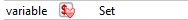
To create a new Variable set:
- Click on the New Metadata button in the Project Explorer toolbar. The New Model wizard opens.
- Select the Variable Set type.
- Choose a name and a folder to store the metadata file. The metadata file will be created
Creating the Variables
To create a new Variable:
- Right-Click on the Set node and choose New Child and Variable.
- In the properties tab, give a name to the Variable
Variables properties
| Name | Mandatory | Description |
|---|---|---|
| Name | yes | Name of the Variable |
| Type | Type of the Variable: String, Integer, Boolean or Float. The default value will be String. | |
| Refresh Query | Used if a Refresh Connection is defined. This query will be executed to retrieve a value for the Variable. In case of a query returning multiple rows or multiple columns (or both), the first column of the first row will used as the value | |
| Default Value | The default value of the Variable | |
| Saving Connection | Connection used to save the values of the Variable. A connection should be defined first. See below for more information. | |
| Refresh Connection | Connection used by the Refresh Query. A connection should be defined first. See below for more information. | |
| Default Operation | Operation used when invoking the Variable Manager. |
Associating connections to Variables
Connections can be defined and shared in the Variable Set.
This will allow
- to get values for the variable using a SQL order, through a refresh query defined on the variable
- to save and get the values of the Variables in a table
Defining a connection
To define a connection:
- Right-Click on the Set node and choose New Child and Connection.
- Give a name to the connection
- Drag and drop under the connection the metadata that you want to use for this connection.
Note: You can add several connections in the Variable Set.
Tip: You can use different types of metadata nodes in the connection: a server, a schema, a table or even a column. This can be useful to generate the proper SQL order for the refresh query.
Saving and Refreshing connections
Once the connections are defined in the Variable Set, they can be used to refresh or save the values of the Variables.
The Refresh and the save connections can be defined for each variable in the properties tab in its own combo box.
The Refresh and the save connections can also be defined on the Set node. In this case, all the variables for which connections are not defined will use these connections.
Using the metadata to generate proper SQL Orders
The node that has been defined on the connection can be used to generate the SQL orders.
The node, in fact, is a link to the Metadata.
In the Refresh Query, you can use the XPath or metadata functions provided by Stambia directly inside the { } enclosers.
If the metadata used in the connection is a schema, you can use the following syntaxes:
- To get the Schema name:
{ ./tech:physicalName() }
- To get a qualified name for an object (i.e. a table):
{ ./md:objectPath(.,'MYTABLE') }
If the metadata used in the connection is a table, you can use the following syntax:
{ ./tech:physicalPath() }
Using Metadata Variables in Mappings
To use a Variable in a Mapping:
- Drag and drop the Variable node from the Metadata file into the Mapping. This will add the Variable as a new source in the Mapping.
- In the Mapping, drag and drop the Variable into the target column, the join or the filter expressions in which the Variable should be used.
In the Expression Editor the Variable will automatically have the following syntax:
%{VARIABLE_NAME}%
where VARIABLE_NAME is the name of the variable.
Using Metadata Variables in Processes
To use a Variable in a Process:
- Drag and drop the Variable node from the Metadata file into the Process diagram. This will instantiate the Variable Manager object with a predefined Metadata Link to the Variable. The predefined properties of the Variable will automatically be set on the Variable Manager when the Process will be generated (default value, connections, default Operation ...)
- Modify the properties in the Properties Tab view
Tip: if you want to retrieve a value from a table to parameterize a Mapping, you can instantiate a Variable in a Process as explained above. If the Variable has a Refresh Query, it will be used to retrieve the value. You can then use the Variable in the Mapping as explained in the previous sections.
Syntax to use Metadata Variables in Expressions
In order to use a Variable in an Expression (action text or parameter), you will have to instantiate the Variable in the Process, and use the following syntax:
%{VARIABLE_NAME}%
where VARIABLE_NAME is the name of the variable.
Using Metadata Variables in other Metadata Variables
In order to use a Variable in another Variable, there are two cases:
The two Variables are defined in the same Metadata file
In this case, you will just have to use the following syntax:
%{VARIABLE_NAME}%
where VARIABLE_NAME is the name of the Variable.
This syntax can be used in the query or in the default value.
The two Variables are defined in different Metadata files
In this case, before using the Variable inside another Variable, you will have to link the two Metadata files together:
- Open the destination Metadata file (the file in which is found the Variable that will receive the other Variable)
- Drag & drop the Variable node you want to use from its Metadata file to the opened Metadata file (on the Variable Set node)
- Use the following syntax:
%{VARIABLE_NAME}%
where VARIABLE_NAME is the name of the Variable.
This syntax can be used in the query or in the default value.
Using Metadata Variables in other Metadata
In order to use a variable in other Metadata properties (e.g. a Variable in a table condition), you will have to link the two Metadata files together:
- Open the destination Metadata file (the file in which is found the Metadata that will receive the Variable)
- Drag & drop the Variable node you want to use from its metadata file to the opened Metadata file
- Use the following syntax in the properties:
%{VARIABLE_NAME}%
where VARIABLE_NAME is the name of the Variable.
Working with Substitution Variables
What is a String Substitution Variable?
You can use Eclipse Substitution variables in your expressions.
Those are local workspace variables which can be useful to have expressions dynamically defined from some variables.
You can use the Eclipse predefined variables or add your own.
Those variables are evaluated at generation and when using the different Metadata wizards.
They cannot be externalized, and the generated value will be put as is in generated delivery.
Syntax to use String Substitution Variables in Expressions
You can use a String Substitution variable with the following syntax:
%{env:variable_name}%
Example of Eclipse predefined variables
There is a list of predefined variables which already exist and which are provided by the current installation.
Here is a non-exhaustive list of available variables.
Refer to Eclipse documentation for the exact list of existing predefined variables.
| Name | Description |
|---|---|
| eclipse_home | Absolute path to current Designer installation folder. |
| workspace_loc | Absolute path to current workspace folder. |
| project_name | Name of the Project from which the value is generated. |
| project_loc | Absolute path of the Project from which the value is generated. |
| resource_name | Name of the resource from which the value is generated, which can be for instance the name of the Process in which the value is generated. |
| resource_loc | Absolute path of the resource from which the value is generated, which can be for instance the path of the Process in which the value is generated. |
Example:
%{env:project_name}%
Example of user defined variables
You can also define your own Substitution variable.
For this, go to the following Menu in Designer, and define your own variables:
Window > Preferences > Run/Debug > String Substitution
User defined variables can be used the same way as predefined variables:
%{env:custom_variable_name}%
Working with Restart Points
When a process failed (with an error or a killed status), it can be restarted.
By default, it will restart from the steps that had an error status.
In a process you can also open and close "Restart Points" to define other ways to restart.
In case you have defined Restart Points, if the process fails without reaching the step on which the Restart Point is closed, the process will restart from the Restart Point above the failed step.
Note that you can have several Restart Points. If the process fails, it will restart, for each failed step, on the last Restart Point above the failed step.
Opening a restart point
To open a restart point:
- Right-Click on the step in the process
- Choose «Restart Point» and "open"
- This will add the following icon:

Closing a restart point
To close a restart point:
- Right-Click on the step in the process
- Choose «Restart Point» and "close"
- This will add the following icon:

What’s New
What’s New in Stambia DI 2020 (S20)
About this version
Stambia DI 2020 (S20) is a major release coming with a lot of improvements.
This new version is adding new mechanisms to ease the installation of Components, ease the installation of third party libraries, and more!
When coming from prior version, there are important points to have in mind when you want to migrate to this version.

We highly advise to read carefully the complete release notes at the following location:
Stambia DI Designer 2020 (S20) release notes
Stambia DI Runtime 2020 (S20) release notes
And also the migration guide at the following location:
Designer Migration guide
Runtime Migration guide
Overview
You can find below a quick overview of the new features.
| Feature | Description |
|---|---|
| Platform Update | The Designer is based on Eclipse platform. The platform on which it is based as been updated to latest version to support Java version higher than Java 8 and to benefit of all the platforms fixes, such as performances, stability and graphical fixes. Note that the Designer now requires Java 8 or higher. |
| Components revised | We revised the installation and packaging of all our Components to have all in one Components containing everything required. A Component now contains technologies, Templates, Modules, documentation and sample projects. Installing a Component will install all of those and updating a Component will update everything. The Installation now consists of downloading the archive file of a Component and install it in a few clicks directly from the Designer. For instance, installing Elasticsearch Component will install automatically the Elasticsearch Technologies, Templates, Modules, Sample Projects, and more... at once, from one unique archive. |
| Templates integrated | The Templates are now shipped and installed in the Designer automatically when installing Components. They are imported in internal resources, you do not need anymore to import Templates in your workspace. |
| Sample Projects integrated | Sample Demonstration Projects are now shipped within the Designer and in additional Components. You’ll be able to import them to play with examples in a few clicks from the new Welcome Page. |
| Welcome page | The Welcome Page has been revisited to show a quick overview to easily access tutorials, documentation, and also to import in a few click the sample projects available in the current installation. The available sample projects are coming from the base installation and also the additional Components installed. |
| Modules | One of the major improvements is the modularization of libraries. When you need to use a technology, you need to have the necessary libraries to communicate with it, such as JDBC drivers for instance. There is now a whole new mechanism to install and compartmentalize all the libraries required. See the releases notes and complete documentation for further information. |
| Metadata improvements | A lot of usability improvement have been performed, do not hesitate to have a look at the release notes for further information. |
| Mapping Stage on the fly | Creating Mapping stages is now simpler as ever: you can create a stage on the fly by drag and dropping fields from a datastore directly. In a Mapping, select the fields from your source datasource, and drag and drop them in the editor. A new popup will appear asking to choose between creating a filter or stage. In the stage menu, you can browse all the possible staging area of your workspace, and you can also define your preferred locations that will appear in the context menu automatically. |
| Extra Nodes | On Metadata such as File, XML, or JSON, you can define advanced property fields to retrieve in Mappings for instance the file name, the xml current node name or position, etc. You can now create them dynamically in Mappings, without having to create them before in your Metadata. In Mapping, when applicable, a small button will allow you to add extra fields on the selected node. For instance, in a Mapping, you’ll be able to select the root node of a File datastore and click on the button to add all the extra fields you want. |
| Process Palette | Process palette has been enhanced. It can now contain custom tools which will be automatically filled when installing Components for instance. You will find back in Process Palette the Replicators, Reject Templates, etc, and all Templates and tools provided by the installed Components. |
| Runtime Delivery Pulling | The Runtime now supports pulling deliveries from Analytics 3.x |
| Runtime new FTP Command Process Action | A new Process Action to execute FTP Commands has been added, replacing the previous one which supported only Raw FTP Commands. The new FTP Command Process Action now supports also using most commonly used commands aliases. |
| And more... | Stambia DI 2020 (S20) includes other improvements and fixes which can be found in the release notes and changelogs. |